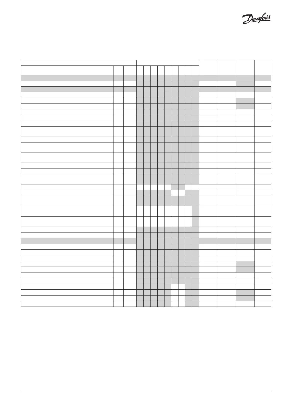
Menu survey
SW = 2.0x
Menu set via display
R-W
If the operation is limited by a setting of one or more passwords, reading and setting the
parameter will be limited to:
R: This setting can be seen with password no. _ or higher.
W: This setting can be performed with password no. _ or higher (3 is the highest level).
*) Always required that the regulating is stopped, r12=0)
**) Always required that the regulating is stopped and set to manual service, r12= -1)
Parameter Wiring diagram pages 2-4
Min. value Max. value
Factory
setting
Actual
setting
Function R-W Code 1 2 3 4 5 6 7 8 9
Normal operation
Temperature (setpoint) 0-0 r00 1 1 1 1 1 1 1 1 1 "r03" "r02" 2
Thermostat
Differential
1-2 r01 1 1 1 1 1 1 1 1 1 0.1 K 20 K 2
Max. limitation of setpoint setting
0-2 r02 1 1 1 1 1 1 1 1 1 "r03" 50 °C 50
Min. limitation of setpoint setting
0-2 r03 1 1 1 1 1 1 1 1 1 -50 °C "r02" -50
Temperature unit (°C/°F)
1-2 r05 1 1 1 1 1 1 1 1 1 0/°C 1/F 0/°C
Correction of the signal from S4
1-2 r09 1 1 1 1 1 1 1 1 1 -10 K 10 K 0
Correction of the signal from S3
1-2 r10 1 1 1 1 1 1 1 1 1 -10 K 10 K 0
Manual service, stop regulation, start regulation (-1,
0, 1)
0-2 r12 1 1 1 1 1 1 1 1 1 -1 1 0
Displacement of reference during night operation
1-2 r13 1 1 1 1 1 1 1 1 1 -50 K 50 K 0
Define thermostat function
1=ON/OFF, 2=Modulating
1-2 r14 1 1 1 1 1 1 1 1 1 1 2 1
Definition and weighting, if applicable, of thermostat
sensors - S4% (100%=S4, 0%=S3)
1-2 r15 1 1 1 1 1 1 1 1 1 0 % 100 % 100
Time between melt periods 1-2 r16 1 1 1 1 1 1 1 1 1 0 hrs 10 hrs 1
Duration of melt periods 1-2 r17 1 1 1 1 1 1 1 1 1 0 min. 30 min. 5
Temperature setting for thermostat band 2 . As dif-
ferential use r01
0-2 r21 1 1 1 1 1 1 1 1 1 -50 °C 50 °C 2
Correction of the signal from S3B 1-2 r53 1 1 -10 K 10 K 0
Correction of the signal from S6 1-2 r59 1 1 1 1 1 1 1 -10 K 10 K 0
Definition and weighting, if applicable, of thermostat
sensors when night cover is on. (100%=S4, 0%=S3)
1-2 r61 1 1 1 1 1 1 1 1 1 0 % 100 % 100
Heat function
Neutral zone between refrigeration and heat function
1-2 r62 1 0 K 50 K 5
Time delay at switch between refrigeration and heat
function
1-2 r63 1 0 min. 240 min. 240
Food type: use settings listed in table. 1-2* r89 1 1 1 1 1 1 1 1 1 0 5 0
Min. limit for S4 temperature 1-2 r98 1 1 1 1 1 1 1 1 1 -50 °C 50 °C -50
Alarms
Delay for temperature alarm 1-2 A03 1 1 1 1 1 1 1 1 1 0 min. 240 min. 30
Delay for door alarm 1-2 A04 1 1 1 1 1 1 1 1 1 0 min. 240 min. 60
Delay for temperature alarm after defrost 1-2 A12 1 1 1 1 1 1 1 1 1 0 min. 240 min. 90
High alarm limit for thermostat 1 1-2 A13 1 1 1 1 1 1 1 1 1 -50 °C 50 °C 8
Low alarm limit for thermostat 1 1-2 A14 1 1 1 1 1 1 1 1 1 -50 °C 50 °C -30
High alarm limit for thermostat 2 1-2 A20 1 1 1 1 1 1 1 1 1 -50 °C 50 °C 8
Low alarm limit for thermostat 2 1-2 A21 1 1 1 1 1 1 1 1 1 -50 °C 50 °C -30
High alarm limit for sensor S6 at thermostat 1 1-2 A22 1 1 1 1 1 1 1 -50 °C 50 °C 8
Low alarm limit for sensor S6 at thermostat 1 1-2 A23 1 1 1 1 1 1 1 -50 °C 50 °C -30
High alarm limit for sensor S6 at thermostat 2 1-2 A24 1 1 1 1 1 1 1 -50 °C 50 °C 8
Low alarm limit for sensor S6 at thermostat 2 1-2 A25 1 1 1 1 1 1 1 -50 °C 50 °C -30
© Danfoss | DCS (vt) | 2019.07
10 | AN294432763974en-000201
 Loading...


