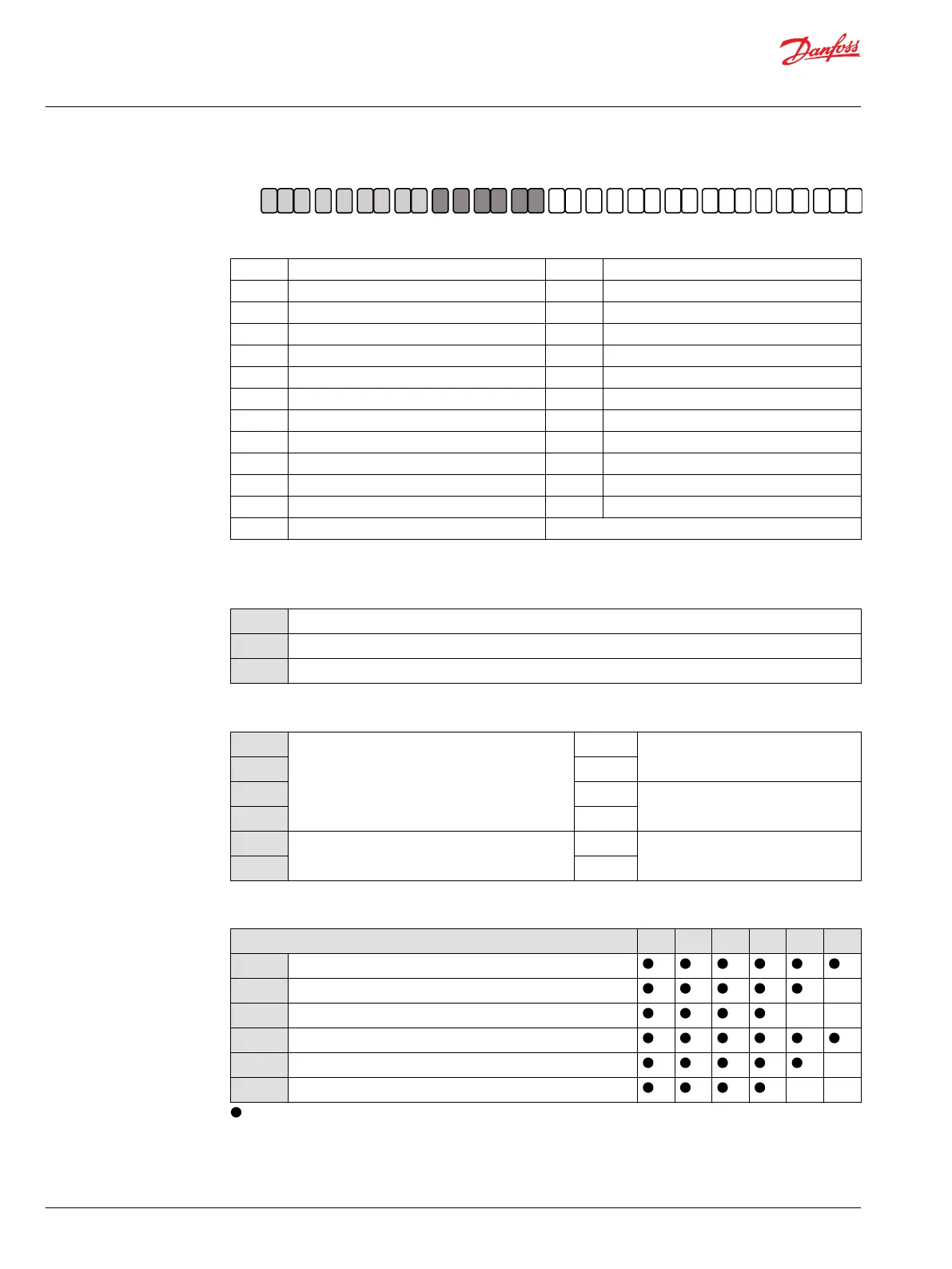
A B C D E F G H J K L M N P Q R
H1 B
A
Z
A
N N N N N
D – Threshold setting (Hydraulic adjustment)
A 2 bar [29 psi] N Non applicable
B 3 bar [43.5 psi] O 15 bar [217.6 psi]
C 4 bar [58 psi] P 16 bar [232.1 psi]
D 5 bar [72.5 psi] Q 17 bar [246.6 psi]
E 6 bar [87 psi] R 18 bar [261 psi]
F 7 bar [101.5 psi] S 19 bar [275.6 psi]
G 8 bar [116 psi] T 20 bar [290 psi]
H 9 bar [130.5 psi] U 22 bar [319 psi]
I 10 bar [145 psi] V 24 bar [348 psi]
J 11 bar [159.5 psi] W 26 bar [377.1 psi]
K 12 bar [174 psi] X 28 bar [406.1 psi]
L 13 bar [188.5 psi] Y 30 bar [435 psi]
M 14 bar [203 psi]
All options are intended to be used for DH, LH, MH, KH controls, except N - Non applicable.
E – Orifices (M4 and M5)
A
Ø1.2 mm [Dia 0.047 in]
B
Ø0.8 mm [Dia 0.031 in]
C
Ø0.6 mm [Dia 0.024 in]
F – Endcap type and ports per ISO 6162, type 1 (metric)
PA
Endcap for proportional controls
axial port
Use with controls: L*, LH, D* and DH
PB
side port
RA
axial port
Use with controls: M*, MH, K* and KH
RB
side port
TA
Endcap for 2-position and PCOR controls
axial port
Use with controls:
E*, F*, H*, T*, P*, TH, HE and HF
TB
side port
G – Flange and housing
Size 060 080 110 160 210 250
VN
SAE flange motor housing (ISO 3019/1), no speed sensor port
DN
DIN flange motor housing (ISO 3019/2), no speed sensor port –
CN
Cartridge flange motor housing, no speed sensor port – –
VS
SAE flange motor housing (ISO 3019/1), with speed sensor port
DS
DIN flange motor housing (ISO 3019/2), with speed sensor port –
CS
Cartridge flange motor housing, with speed sensor port – –
= available option, – = not available option
Technical Information
H1 Bent Axis Variable Displacement Motors, Size 060/080/110/160/210/250
Master Model Code
32 |
©
Danfoss | December 2016 11037153 | BC00000043en-US1103
 Loading...


