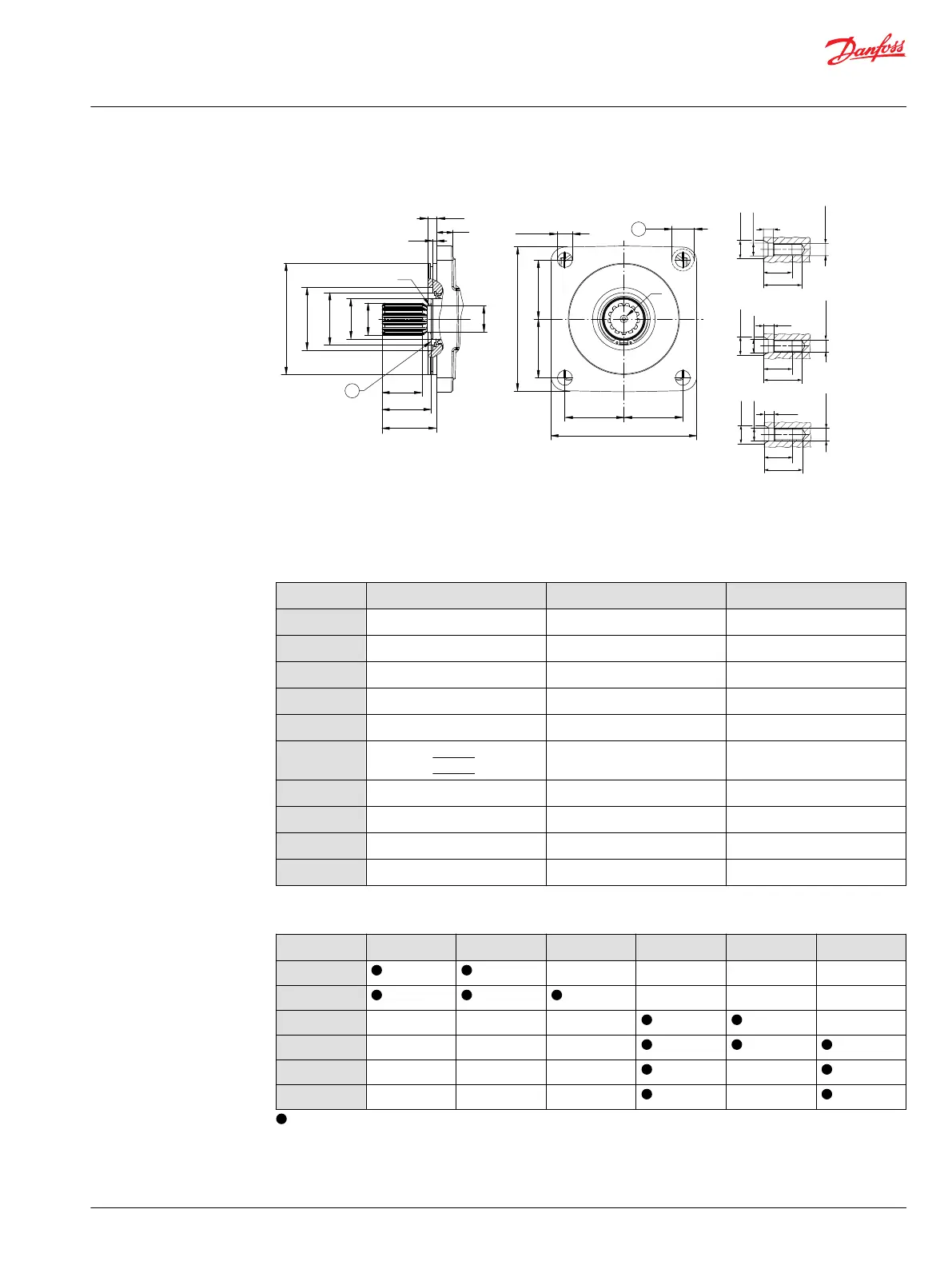
SAE mounting flange design per ISO 3019/1
ØA
ØJ
ØH
ØG
ØF
ØB
DB
DA
DC
DE
R
DH
DJ
P003 445
1
DK
DL
DLDL
DK
DL
DM
(4x)
DN (4x)
V
2
23
31
8
V (M10)
∅14.9
∅10.5
M10x1.5
29
38
10
V (M12)
∅18.1
∅13
M12x1.75
38
44
12.5
V (M16)
∅23
∅17
M16x2
1. Coupling must not protrude beyong this surface
2. Maximum screw head space other side
SAE flange dimensions mm [in]
Measure Size 060/080 – Flange 127-4 Size 110/160 – Flange 152-4 Size 210/250 – Flange 165-4
ØB
126.975 [4.999] 152.375 [5.999] 165.075 [6.5]
ØF
80 [3.15] 86 [3.386] 100 [3.937]
ØG
62 [2.441] 72 [2.835] 72 [2.835]
DE
6.4 [0.252] 6 [0.236] 6.4 [0.252]
DH
12.5 [0.492] 12.5 [0.492] 15.65 [0.62]
DJ
18 [0.709] - size 060
19 [0.748] - size 080
22.0 [0.866] 25 [0.98]
DK
142.5 [5.61] 200 [7.874] 260.0 [10.24]
DL
57.3 [2.256] 80.8 [3.181] 112.2 [4.42]
DM
19.5 [0.768] 30 [1.181] 30 [1.181]
DN
14.3 [0.563] 20.6 [0.811] 20.6 [0.811]
Shaft options overview (Number of teeth)
Size
AN/AS (14T) BN/BS (21T) CN/CS (23T) DN/DS (27T) EN/ES (13T) FN/FS (15T)
060
— — — —
080
— — —
110
— — — —
160
— — —
210
— — — —
250
— — — —
= available option, – = not available option
Technical Information
H1 Bent Axis Variable Displacement Motors, Size 060/080/110/160/210/250
Dimensions
©
Danfoss | December 2016 11037153 | BC00000043en-US1103 | 97