© Danfoss | DCS (ms) | 2020.01
AN19798642980802-000701 | 5
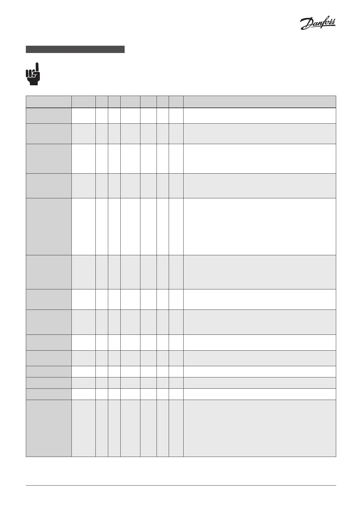
Parameter list - Valid from: (¡58:14, ¡59:45) and onwards
Description
ICAD
parameter
Min Max
Factory
Setting
Stored Unit
Pass
word
Comments
OD (Opening degree) - 0 100 % -
ICM/ICMTS valve Opening Degree (CVE pressure setting) is displayed during normal
operation.
Running display value (see ¡01, ¡05).
Main Switch ¡01 1 2 1
- No
Internal main switch
1: Normal operation
2: Manual operation. Valve Opening Degree will be flashing. With the down
arrow and the up arrow push buttons the OD can be entered manually.
Mode ¡02 1 2 1
- No
Operation mode
1: Modulating – ICM, ICMTS & CVE positioning according to Analog Input (see ¡03)
2: ON/OFF - ICM only. Operating the ICM valve like an ON/OFF solenoid valve
controlled via Digital Input. See also ¡09.
3: Neutralzone / 3 point control - ICM only. Increase/Decrease Opening Degree by
Digital Input. See fig. 9
AI signal ¡03 1 4 2
- No
Type of AI signal from external controller
1: 0 – 20 mA
2: 4 – 20 mA
3: 0 – 10 V
4: 2 – 10 V
Speed
In Modulating Mode
Opening/closing
speed
In ON/OFF Mode
Opening speed
In Neutralzone/
3 point control
Opening speed = 10
¡04 1 100 50/ 100
- No
Speed can be decreased. Max. speed is 100 % - Not active in manual operation (¡01 = 2)
For CVE the speed should not exceed 50 (factory setting)
If ¡26= 1 - 3 then factory setting =100
If ¡26= 4 - 10 then factory setting =50
If the valve is opening and (¡04 < = 33) or the valve is closing and (¡14 < = 33)
=> Low is displayed.
If the valve is opening and (33 < If ¡04 < = 66) or the valve is closing and (33 < If ¡14 < = 66)
=> Med is displayed.
If the valve is opening and (¡04 > = 67) or the valve is closing and (¡14 > = 67)
=> High is displayed"
Automatic calibration ¡05 0 2 0 - No
Not active before ¡26 has been operated.
Always auto reset to 0.
CA will flash in the display during calibration,
if Enter push button has been activated for two seconds
0: No Calibration
1: Normal forced calibration - CA flashing slowly
2: Extended calibration – CA flashing rapidly"
AO signal ¡06 0 2 2
- No
Type of A0 signal for ICM valve position
0: No signal
1: 0 – 20 mA
2: 4 – 20 mA
Failsafe ¡07 1 4 1
- No
Define condition at power cut and fail safe supply is installed.
1: Close valve
2: Open Valve
3: Maintain valve position
4: Go to OD given by ¡12"
Fail safe supply ¡08 0 1 0
Yes
Fail safe supply connected and enable of A4 alarm:
0: No
1: Yes
DI function ¡09 1 2 1
No
Define function when DI is ON (short circuited DI terminals) when ¡02 = 2
1: Open ICM valve (DI = OFF = > Close ICM valve)
2: Close ICM valve (DI = OFF = > Open ICM valve)
Password ¡10 0 199 0 - -
Enter number to access password protected parameters: ¡26
Password = 11
Old Alarms ¡11 A1 A99 - - No
Old alarms will be listed with the latest shown first. Alarm list can be reset by means
of activating down arrow and up arrow at the same time for 2 seconds.
OD at power cut. ¡12 0 100 50
No
Only active if ¡07 = 4
If fail safe supply is connected and power cut occurs, the valve will go to the specified OD.
Inverse operation ¡13 0 1 0
No
When ¡02 = 1
0: Increasing Analog Input signal => Increasing ICM Opening Degree
1: Increasing Analog Input signal => Decreasing ICM Opening Degree
When ¡02 = 3
0: DI1 = ON, DI2 = OFF => Increasing valve Opening Degree.
DI1 = OFF, DI2 = ON => Decreasing valve Opening Degree
DI1 = DI2 = OFF => ICAD/ICM maintain current position
DI1 = DI2 = ON => ICAD/ICM maintain current position
1: DI1 = ON, DI2 = OFF => Decreasing ICM Opening Degree
DI1 = OFF, DI2 = ON => Increasing ICM Opening Degree
DI1 = DI2 = OFF => ICAD/ICM maintain current position
DI1 = DI2 = ON => ICAD/ICM maintain current position
The first parameter to be entered shall be: ¡26
to be continued....
ENGLISH
 Loading...