Do you have a question about the Danfoss MCX Series and is the answer not in the manual?
Identifies the MCX152V, MCX08M, and MMIGRS2 models.
Details on connectivity, CE, and UL compliance.
Specifies power requirements and consumption.
Details on Digital Outputs, Analog Outputs, and Inputs.
Explains Modbus cable requirements and topology rules.
Instructions for setting the baud rate with AK-SM800.
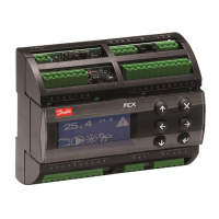
The Danfoss MCX rooftop controller is a sophisticated device designed to manage and optimize the operation of rooftop HVAC (Heating, Ventilation, and Air Conditioning) systems. This controller serves as the central intelligence for a wide range of functions, ensuring efficient and reliable performance of the HVAC unit. Its primary role is to provide precise control over various components, including compressors, fans, dampers, and heating elements, to maintain desired indoor environmental conditions while minimizing energy consumption.
The MCX rooftop controller integrates a comprehensive set of inputs and outputs to interact with the HVAC system and its environment. It features a variety of analog and digital inputs that allow it to monitor critical parameters such as temperature (using PT1000 sensors), pressure (via ratiometric transducers), humidity, CO2 levels, and fan current. These inputs provide the controller with real-time data about the system's operational status and the prevailing environmental conditions, both indoors and outdoors. For instance, temperature sensors monitor mixed air, outdoor air, return air, supply air, and zone temperatures, enabling the controller to make informed decisions about heating and cooling demands. Pressure transducers monitor compressor pressures, which are crucial for optimizing refrigeration cycles and detecting potential issues. Digital inputs are used to detect the status of various components, such as fan proof, phase loss, shutdown conditions, drive faults for compressors and fans, filter clogging, and override signals.
Based on the data received from these inputs, the MCX controller utilizes its internal logic and programmed algorithms to activate its digital and analog outputs. Digital outputs, primarily relays, control on/off functions for components like compressors, fans (low and high speed), heating elements (reheat, aux heat), and dampers. Analog outputs provide proportional control, for example, to modulate dampers for precise airflow management or to control variable speed compressors for fine-tuned capacity adjustment. This allows the controller to dynamically adjust the HVAC system's operation to meet specific setpoints for temperature, humidity, and CO2, ensuring optimal comfort and air quality.
The controller also supports Modbus communication, enabling it to be integrated into larger building management systems (BMS) or networked with other controllers and devices. This communication capability allows for remote monitoring, control, and data logging, enhancing the overall management of the HVAC system. The Modbus topology requires careful installation of EIA485 rated cables, with considerations for cable length, the need for repeaters in noisy environments or over long distances, and proper termination of the bus. The controller's baud rate for Modbus RTU communication is configurable, typically set to 38.4 K when used with devices like the AK-SM800.
The MCX rooftop controller is designed for ease of use and flexibility in various HVAC applications. Its comprehensive set of inputs and outputs means it can be adapted to control a wide range of rooftop unit configurations, from basic single-stage systems to more complex multi-stage and variable capacity units. The ability to monitor multiple temperature zones, CO2 levels, and humidity allows for sophisticated zone control, providing customized comfort in different areas of a building.
The controller's support for various sensor types, including PT1000 for temperature and ratiometric transducers for pressure, ensures compatibility with standard industry components. The default settings for analog inputs, such as PT1000 for temperature and 0.5-4.5 V DC for pressure transducers, simplify initial setup. Similarly, analog outputs default to 0-10V DC, providing a common interface for modulating devices.
Digital inputs are versatile, accommodating both dry contacts and 24 V AC or 230 V AC driven signals, which allows for integration with various types of switches and status indicators. This flexibility extends to the digital outputs, which are all relays, providing robust switching capabilities for different loads.
The optional MCX08M and MMIGRS2 modules further expand the controller's capabilities, offering additional inputs, outputs, or specialized functions as needed for more complex systems. The presence of a memory card slot (SD/MMC) suggests potential for data logging, firmware updates, or configuration storage, enhancing the controller's utility and maintainability.
The design of the MCX rooftop controller incorporates several features that contribute to its maintainability and diagnostic capabilities. The detailed wiring diagrams provided in the manual are essential for installation, troubleshooting, and maintenance. These diagrams clearly label each input and output, making it easy for technicians to identify connection points for sensors, actuators, and communication lines.
The controller's ability to monitor various fault conditions through its digital inputs (e.g., fan drive fault, compressor drive fault, filter clogged fault, phase loss, shutdown conditions) is a crucial maintenance feature. By detecting these issues early, the controller can alert maintenance personnel, allowing for proactive intervention before minor problems escalate into major system failures. This diagnostic capability helps in reducing downtime and repair costs.
The Modbus communication interface is also a significant maintenance tool. It allows technicians to remotely access the controller's data, view operational parameters, check alarm statuses, and even modify settings without needing to be physically present at the rooftop unit. This remote access streamlines troubleshooting and allows for efficient system optimization. The requirement for proper Modbus cable installation and termination, as detailed in the manual, is a key aspect of ensuring reliable communication, which is vital for effective remote maintenance.
The mention of an "Instruction guide" and "Installation guide" indicates that comprehensive documentation is available to assist with both initial setup and ongoing maintenance. Furthermore, the reference to the AK-SM800 User Guide for system 485 wiring instructions and its availability online (http://food-retail.danfoss.com/knowledge-center/software/ak-sm-800/) highlights Danfoss's commitment to providing accessible resources for users and technicians. This readily available information empowers maintenance staff to effectively manage and service the MCX rooftop controller and the associated HVAC system.
| Enclosure Rating | IP20 |
|---|---|
| Housing Material | Plastic |
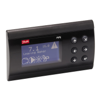
| Display | LCD |
| Communication Ports | RS-485 |
| Inputs | Digital and Analog |
| Outputs | Relay and Analog |
| Power Supply | 24 V AC/DC |
| Protocols | Modbus RTU |
| Relative Humidity | 5% to 95% (non-condensing) |
| Storage Temperature | -40 to +70°C |
| Protection Class | Class II |