Installation
4.3 Wiring diagrams
OP-MPLM028-035-044, OP-MPPM028-035-044
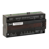
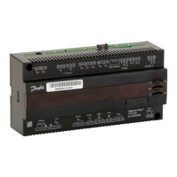
A1 : EMC/RFI Filter (Compressor) A2 : Frequency Converter A3 : EMI Filter (Controls) A4 : Optyma
™
Plus Controller
B1 : Condensing Pressure Transducer B2 : Suction Pressure Transducer B3 : High Pressure Switch B4 : Low Pressure Switch
C1 : Run Capacitor (Fan) F1 : Fuse (Control Circuit) K1 : Contactor M1 : Compressor
M2 : Fan Motor Q1 : Main Switch R1 : Ambient Temp. Sensor R2 : Discharge Temp. Sensor
R3 : Suction Temp. Sensor R4,R5 : Auxiliary Temp. Sensor (optional) R6 : Crankcase Heater R7 : Oil Separator Heater
S1 : Room Thermostat (optional) X1 : Terminal
Supply : Supply Fan : Fan Alarm : Alarm Comp. : Compressor
CCH : Crankcase Heater Aux : Auxiliary
19FRCC.PC.044.A6.02
Application Guidelines
 Loading...
