CAN system design
All PLUS+1
®
modules have CAN ports that conform to CAN 2.0B specifications, including CAN shield.
CAN1 port and CAN2 port on MC050-155/15B controllers cannot be used to download PLUS+1
®
GUIDE
application programs.
Specifications for terminating resistor
Each end of the main backbone of the CAN bus must be terminated with an appropriate resistance to
provide correct termination of the CAN_H and CAN_L conductors. This termination resistance should be
connected between the CAN_H and CAN_L conductors.
Specifications
Description Units Minimum Maximum Nominal Comment
Resistance Ω 110 130 120 Minimum power dissipation 400 mW
(assumes a short of 16 Vdc to CAN_H).
Inductance µH 1
Notes on CAN Bus installation
Total bus impedance should be 60 Ω.
The CAN transceiver will be damaged by any voltage outside of allowable range, (-27 to +36 Vdc), even
with a very short pulse.
If using shielded cable, the shield must be grounded to the machine ground at one point only; preferably
at the mid-point of the CAN bus. Each PLUS+1
®
module CAN shield pin must be connected to the cable
shield.
Expansion module CAN Bus loading
System designers incorporating PLUS+1
®
expansion modules in their applications should be aware of
PLUS+1
®
CAN bus loading and controller memory usage during system design. Each expansion module is
associated with a PLUS+1
®
controller and uses part of the controller's memory resources for inter-module
communications. The following table can be used to estimate system CAN bus loading and the memory
impact of I/O modules on their associated controller.
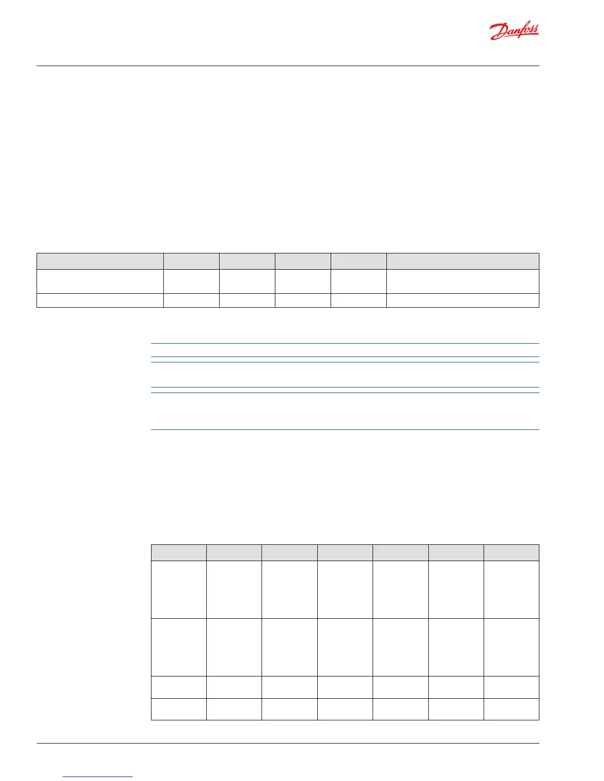
Estimated usage of memory and communication resources
Description IX012-010 IX024-010 OX012-010 OX024-010 IOX012-010 IOX024-20
Estimated
module bus
load (using
default update
and 250K bus
speed)
4% 10% 11% 27% 11% 27%
Estimated
module bus
load (using 70
ms updates
and 250K bus
speed)
2% 5% 3% 8% 4% 8%
RAM usage on
MC012-XXX
9% 12% 9% 14% 9% 17%
RAM usage on
MC024-010
9% 12% 9% 14% 9% 17%
Technical Information
PLUS+1® MC0XX-1XX Controller Family
Controller Area Network (CAN)
18 |
©
Danfoss | April 2018 L1321895 | BC00000227en-US0401