Do you have a question about the Danfoss PLUS+1 Series and is the answer not in the manual?
Lists changes made to the document over different dates and their corresponding revision codes.
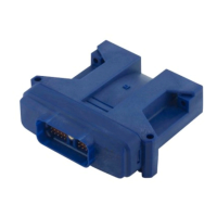
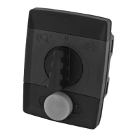
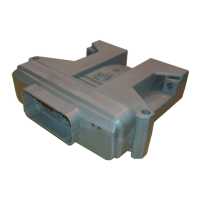
Overview of the PLUS+1 controllers and expansion modules for off-highway vehicles.
Defines the responsibilities of the Original Equipment Manufacturer (OEM) for Danfoss products.
Specifies voltage thresholds, response times, and impedance for digital input pins.
Details voltage ranges, precision, and impedance for analog input pins.
Covers input configurations for analog, temperature, and rheostat functions.
Characteristics of digital, analog, and frequency inputs for specific module types.
Details digital, analog, and frequency input characteristics for IX012-010 and IX024-010.
Specifications for inputs configured for 4-20mA current signals.
Details on standard digital output functionality and current ratings.
Information on digital outputs providing reference power for PVG valves.
Specifications for high current digital outputs capable of sourcing up to 6A.
Details on PWM outputs for proportional control, including operating modes.
Information on high current PWM outputs, unique to MC038-010 controller.
Explains the different output pin power supply designs for specific controller models.
Details CAN port specifications, system design considerations, and warnings.
Specifies the required resistance for proper CAN bus termination.
Guidelines for installing the CAN bus, including voltage limits and shielding.
Estimates memory and communication resource usage for expansion modules.
Specifies module supply voltage ranges and maximum current ratings.
Wiring and power supply recommendations for the MC038-010 controller.
Describes the sleep mode feature and its current consumption for the MC038-010.
Details specifications for dedicated sensor power supply and ground pins.
Information on power supply provision for Danfoss PVG valve electronics.
Specifies the write/erase cycle endurance for EEPROM and FRAM memory.
Describes the serial flash vault memory for application logging.
Details FRAM memory features, including high write endurance for datalogging.
Lists general operating and storage temperature, voltage, and current ratings.
Outlines the standards and conditions for environmental testing of PLUS+1 modules.
Details specific environmental tests like thermal cycle, humidity, and degree of protection.
Specifies resistance to chemical environments based on industry standards.
Details durability against vibration, bump, shock, and free fall.
Covers EMC emission, immunity, ESD, transients, and short circuit protection.
Describes the tamper-proof assembly of PLUS+1 module housings.
Provides part numbers and details for Deutsch mating connectors for PLUS+1 modules.
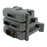
Details methods for installing PLUS+1 modules, including stacking and orientation.
Recommends installing a diagnostic connector for software uploads and service.
Specifies the importance of proper grounding for electronic control systems.
Advises to turn off power before connecting PLUS+1 modules to mating connectors.
Provides best practices for wiring PLUS+1 modules in machine applications.
Recommends procedures for welding on machines equipped with PLUS+1 modules.
Explains the function and setup of the PLUS+1 USB/CAN gateway for PC communication.
| Temperature Range | -40°C to +85°C |
|---|---|
| Ingress Protection | IP67 |
| Communication Interfaces | CAN, Ethernet, USB, RS232, RS485 |
| Operating System | PLUS+1 GUIDE |
| Programming Language | PLUS+1 GUIDE (Graphical User Integrated Development Environment) |
| Memory | Flash, RAM |
| Inputs | Analog, Digital |
| Outputs | PWM, High-Side |
| Protection | Overvoltage, Undervoltage, Reverse Polarity, Short Circuit |
| Operating Voltage | 8-32 VDC |