Specifications
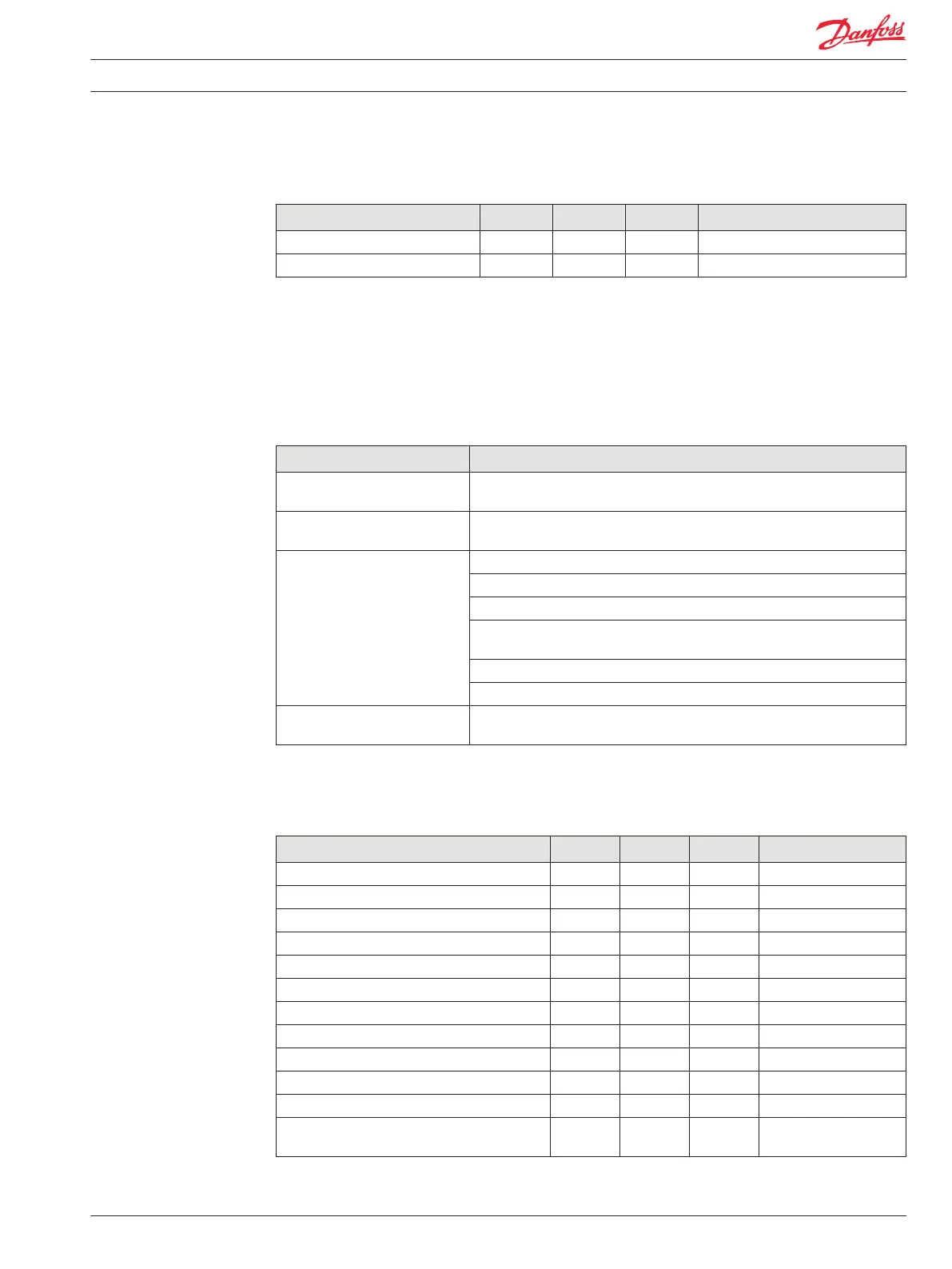
Description Units Minimum Maximum Comment
Allowed voltage at pin Vdc 0 36
Measured resistance Ω 0 10000
Digital/Analog/Frequency(DIN/AIN/FreqIN);Digital/Analog/Frequency/Rheostat(Din/AIN/FreqIN/
Rheo) (All modules except IX012-010, IX024-010)
The characteristics of Digital/Analog/Frequency pins are GUIDE software controlled. The input can be
digital, analog or frequency. Inputs can be pulled to 5 Vdc, pulled to ground, pulled to 2.5 Vdc, or no pull-
up/pull-down.
General
Description Comment
Response to input below
minimum voltage
Non-damaging, non-latching; reading saturates to the low limit.
Response to input above
maximum voltage
Non-damaging, non-latching; reading saturates to the high limit.
Expected measurement Frequency (Hz)
Period (0.1 µsec)
Channel to channel phase shift (paired inputs . . . ) (0.1 ms).
PWM duty cycle (0.01%)—Duty cycle measurement only valid up to 5 kHz
(FreqIN).
xEdge count.
Quadrature count (paired inputs driven from a quadrature encoder).
Pull up/pull down configuration No pull down/ pull up is standard with pull up or pull down programmable;
failure modes are detectable.
As with analog input pins, values in the following table assume software compensation for AD converter
offset errors.
Specifications
Description Units Minimum Maximum Comment
Allowed voltage at pin Vdc 0 36
Frequency range Hz 0 10000 In steps of 1 Hz.
Maximum discernable voltage (high range) Vdc 34.62 35.91 35.3 Vdc is typical.
Maximum discernable voltage (middle range) Vdc 5.18 5.33 5.26 Vdc is typical.
Maximum discernable voltage (low range) Vdc 0.360 0.375 0.368 Vdc is typical.
Precision (high range) mV – – 8.62
Worst case error (high range) mV – – 614
Precision (middle range) mV – – 1.28
Worst case error (middle range) mV – – 75
Precision (low range) µV – – 89.7
Worst case error (low range) mV – – 7.39
Input impedance (pulled to 5 Vdc or ground,
middle and low range)
kΩ 13.9 14.3
Technical Information PLUS+1® Controller Family
Inputs/Outputs Types and Specifications
520L0719 • Rev PB • Feb 2014 11