Specifications (continued)
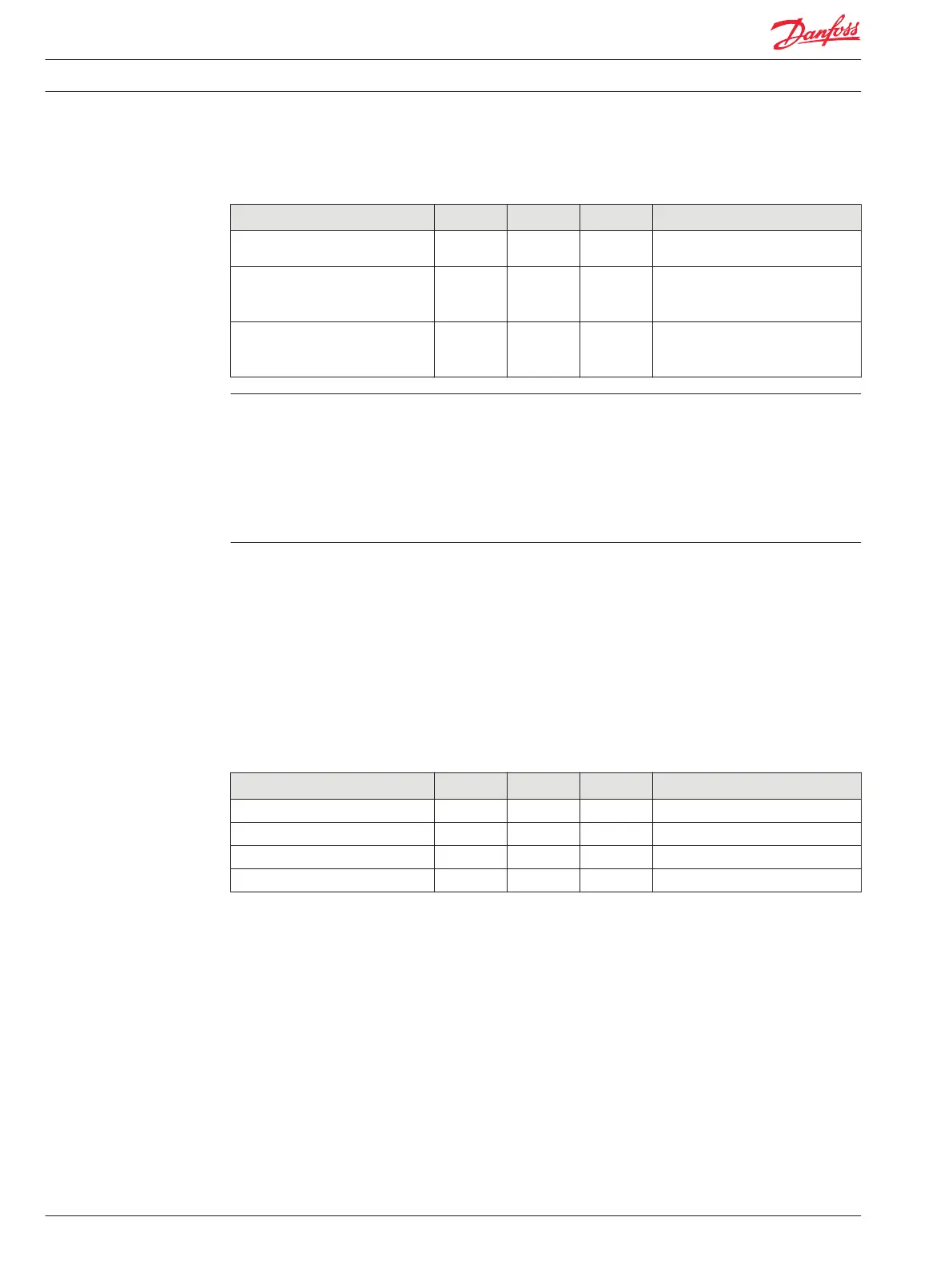
Description Units Minimum Maximum Comment
1.15 Vdc. These numbers also apply
to frequency.
Rising voltage threshold (low range) Vdc 0.22 0.31 A digital input is guaranteed to be
read as high if the voltage is greater
than 0.31 Vdc.
Falling voltage threshold (low
range)
Vdc 0.090 0.20 A digital input is guaranteed to be
read as low if the voltage is greater
than 0.090 Vdc.
Potential for IX modules to not go online. If voltage is applied to an IX module input pin prior to the
module being powered on, there is a possibility that the module CPU will not power up. The module is
not damaged and will power up and operate normally once power is removed from the input pins. It is
recommended that either the IX module’s 5 Vdc sensor power be used to power sensors or that power is
removed from the input pins until the module is powered up.
If the frequency goes to zero, the data will not decay over time, it will be updated once a new pulse is
seen, or times out. It is possible to monitor the count of pulses to know when the frequency reading is
updated.
Digital/Analog/4-20 mA (DIN/AIN/4-20 mA IN)
Refer to Analog/Digital/Frequency Specifications table, page 12, for input properties when pins are
configured as digital, analog or frequency. If the pin is configured to read current, the table below
applies. When interfacing with sensors that transmit a 4 to 20 mA current signal, the positive lead of the
transmitter is connected to battery voltage and the negative lead is connected to the PLUS+1 module
pin. The current measuring configuration relies on the application program to provide over current
protection.
The current measuring configuration is only available on MC088-XXX modules.
Specifications
Description Units Minimum Maximum Comment
Allowed voltage at pin Vdc 0 36
Minimum input current mA 3 4
Maximum input current mA 20 24
Precision µA 5.86
Outputs
Output Types
•
Digital (DOUT)
•
Digital/PVG valve reference power (DOUT/PVGpwr)
•
High current digital (HDOUT)
•
Pulse width modulated (PWM/DOUT/PVGOUT)
•
High current (6 A) pulse width modulated (HPWMOUT/DOUT)
•
High current (10 A) pulse width modulated (HPWMOUT/DOUT)
Technical Information PLUS+1® Controller Family
Inputs/Outputs Types and Specifications
14 520L0719 • Rev PB • Feb 2014