General (continued)
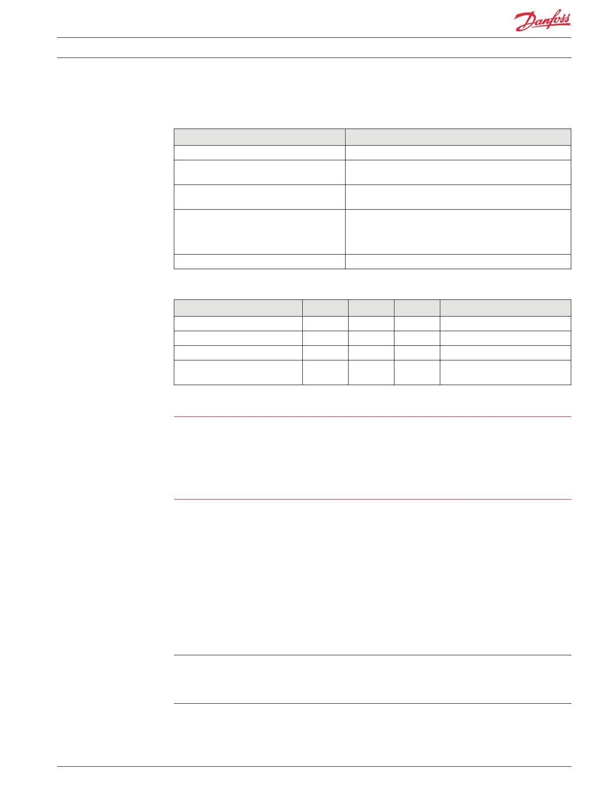
Description Comment
Type Linear switching.
Short circuit to ground protection Non-damage, current/thermal limit with status indication;
automatic latch off/resume.
Open circuit detection Status indication provided. The GUIDE pin status requires a load
of 1000 mA to be connected or an open status will be declared.
Parallel operation Digital outputs from the same module are capable of being
connected together such that the net current rating is the sum of
the individual ratings: timing is resolved by the operating system
and diagnostic capability is maintained.
Shut off Processor control with hardware Watchdog override.
Specifications
Description Units Minimum Maximum Comment
Allowed voltage at pin Vdc 0 36 See caution statement below.
Output voltage, energized state Vdc Vbatt-1.0 Vbatt Over all load conditions.
Output voltage, off state Vdc 0 0.1 At Rload=200 Ω
Output current range for status bit
to read OK
A 1 6 See pair comment above.
Warning
Unintended movement of the machine or mechanism may cause injury to the technician or bystanders.
DOUT and HDOUT digital outputs do not have an internal feedback to the PLUS+1 module kernel. To
protect against unintended movement, if the application requires fault detection, an external feedback
using an AIN configured pin must be used. External feedback is required if the actual output is to be read
by the PLUS+1 Service Tool.
All other output types have internal feedback to the PLUS+1 module kernel that provide pin fault and
status information that can be read directly by the application and the PLUS+1 Service Tool.
Pulse Width Modulated (PWMOUT/DOUT/PVGOUT)
All PLUS+1 Module proportional outputs are Pulse Width Modulated (PWM). PWM frequency is software
adjustable using GUIDE. A low frequency dither may also be added with software to some outputs (see
individual module API specifications for PWM outputs that support dither). There are two modes of PWM
operation: open loop and closed loop (current control).
In open loop mode, current can be sourced or sunk (all modules are limited to 8 amps sinking), but the
output is a PWM duty cycle. Current feedback may be monitored in open loop mode, but the output is a
constant voltage, not a constant current. PVG valves may be driven with open loop PWM.
In closed loop mode, current is sourced and a constant current is maintained by the module’s operating
system using internal current feedback. Load impedance must not exceed 65 ohms.
In closed loop mode, the maximum current is limited by measuring the feedback current. There is no
thermal protection. If the maximum current is exceeded, the controller kernel will shut down the output
and latch it. The kernel also limits how quickly the output can be repowered (250 ms). The output cannot
be reset until the command goes to 0 or False (if configured as a digital output).
Proportional outputs that are used as a digital sinking output have a potential for a leakage current of up
to 5 mA when off.
Technical Information PLUS+1® Controller Family
Inputs/Outputs Types and Specifications
520L0719 • Rev PB • Feb 2014 17