Refer to individual module data sheets for the maximum allowable output current for each PLUS+1
module.
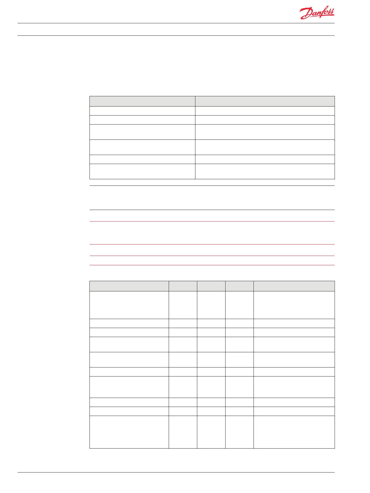
General
Description Comment
Configuration Sourcing or sinking.
Type (Linear vs. PWM) PWM
Operating modes Programmable: closed loop current or open loop voltage (duty
cycle).
Dual coil PCPs Compensated for induced currents in a non-driven coil (closed
loop mode).
Short circuit to ground Output fully protected against damage and fault detected.
Mode selection (current or voltage) and full scale
current ranges
Programmable.
Do not connect a digital output to battery+ (back drive) without a series diode.
PLUS+1 PWM output circuits are not designed to be used as inputs. Output current feedback readings
should be used for fault checking only.
Warning
Unintended movement of the machine or mechanism may cause injury to the technician or bystanders.
The module will be powered up if battery voltage is applied to the module’s output pin. To protect
against unintended movement, secure the machine.
Caution
Warranty will be voided if module is damaged by significant current driven back through an output pin.
Specifications
Description Units Minimum Maximum Comment
Full scale proportional current
output
mA 10 3000 The current may accidently be
exceeded in open loop mode. If the
current exceeds the trip point, the
output will be latched off.
Output voltage, 100% duty cycle Vdc 0 Vbatt-1
Output resolution of 3 A mA 0.25
Repeatability of full range % of full
scale
0.5
Absolute accuracy of full range % of full
scale
0.5
Output settling time ms 100 Depends on load characteristics.
PWM frequency Hz 33 4000 Some pins have a fixed frequency,
consult module application program
interface (API).
Dither frequency Hz 33 250 Increased in steps, see module API.
Dither amplitude A 0 0.5 Increased in steps, see module API.
Over-current trip point A 5 5.25 There is over-current protection built
into each output driver. If the
instantaneous current exceeds the
trip point, the driver is latched off.
GUIDE application software can reset
Technical Information PLUS+1® Controller Family
Inputs/Outputs Types and Specifications
18 520L0719 • Rev PB • Feb 2014