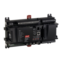
Machine Diagnostic Connector
It is recommended that a diagnostic connector be installed on machines that are controlled by PLUS+1
modules. The connector should be located in the operator’s cabin or in the area where machine
operations are controlled and should be easily accessible.
Communication (software uploads and downloads and service and diagnostic tool interaction) between
PLUS+1 modules and personal computers is accomplished over the vehicle CAN network. The diagnostic
connector should tee into the vehicle CAN bus and have the following elements:
•
CAN +
•
CAN -
•
CAN shield
Grounding
Proper operation of any electronic control system requires that all control modules including displays,
microcontrollers and expansion modules be connected to a common ground. A dedicated ground wire
of appropriate size connected to the machine battery is recommended.
Hot Plugging
Machine power should be off when connecting PLUS+1 modules to mating connectors.
Recommended Machine Wiring Guidelines
1. All wires must be protected from mechanical abuse. Wires should be run in flexible metal or plastic
conduits.
2. Use 85˚ C [185˚ F] wire with abrasion resistant insulation. 105˚ C [221˚ F] wire should be considered
near hot surfaces.
3. Use a wire size that is appropriate for the module connector.
4. Separate high current wires such as solenoids, lights, alternators or fuel pumps from sensor and other
noise-sensitive input wires.
5. Run wires along the inside of, or close to, metal machine surfaces where possible. This simulates a
shield which will minimize the effects of EMI/RFI radiation.
6. Do not run wires near sharp metal corners. Consider running wires through a grommet when
rounding a corner.
7. Do not run wires near hot machine members.
8. Provide strain relief for all wires.
9. Avoid running wires near moving or vibrating components.
10. Avoid long, unsupported wire spans.
11. All analog sensors should be powered by the sensor power source from the PLUS+1 controller and
ground returned to the sensor ground pin on the PLUS+1 controller.
12. Sensor lines should be twisted about one turn every 10 cm [4 in].
13. It is better to use wire harness anchors that will allow wires to float with respect to the machine rather
than rigid anchors.
14. Electronic modules should be grounded to a dedicated conductor of sufficient size that is connected
to the battery (-).
Recommended Machine Equipped with PLUS+1 Module Welding Procedures
The following procedures are recommended when welding on a machine equipped with PLUS+1
modules:
Technical Information PLUS+1® Controller Family
Product Installation and Start-up
520L0719 • Rev PB • Feb 2014 29
 Loading...
