Specifications (continued)
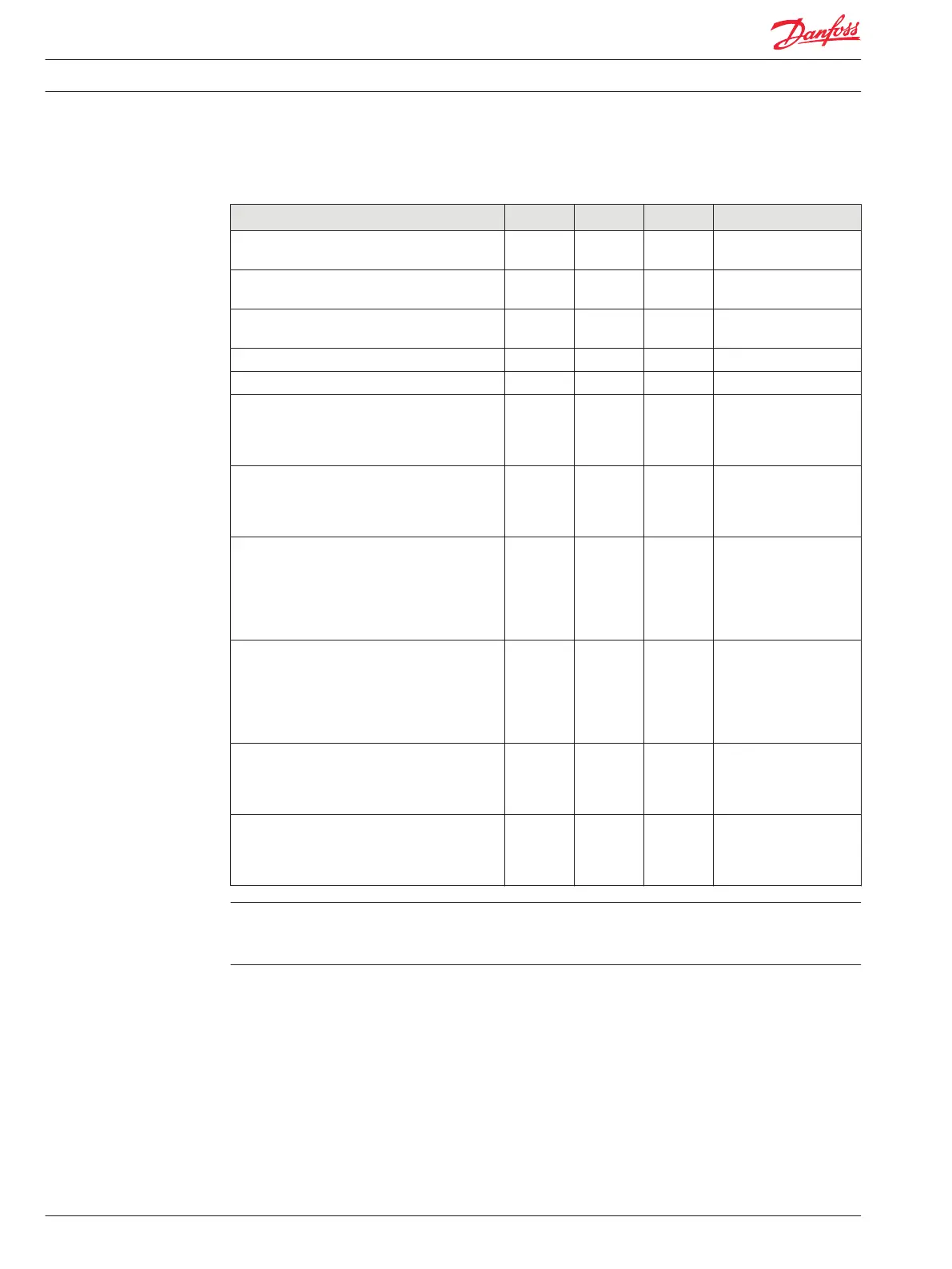
Description Units Minimum Maximum Comment
Input impedance (pulled to 2.5 Vdc middle and
low range)
kΩ 7.17 7.37
Input impedance (no pull ups, middle and low
range)
kΩ 230 236
Input impedance (pulled to 5 Vdc or ground, high
range)
kΩ 13.0 13.4
Input impedance (pulled to 2.5 Vdc high range) kΩ 6.92 7.12
Input impedance (no pull ups, high range) kΩ 108 112
Rising voltage threshold (high range) Vdc 18.9 27.6 It is inadvisable to use the
high range option when
configuring the input as a
digital or frequency input.
Falling voltage threshold (high range) Vdc 6.8 18.5 It is inadvisable to use the
high range option when
configuring the input as a
digital or frequency input.
Rising voltage threshold (middle range) Vdc 2.92 4.12 A digital input is
guaranteed to be read as
high if the voltage is
greater than 3.99 Vdc.
These numbers also apply
to frequency.
Falling voltage threshold (middle range) Vdc 1.02 2.75 A digital input is
guaranteed to be read as
low if the voltage is less
than 0.96 Vdc. These
numbers also apply to
frequency.
Rising voltage threshold (low range) Vdc 0.197 0.298 A digital input is
guaranteed to be read as
high if the voltage is
greater than 0.28 Vdc.
Falling voltage threshold (low range) Vdc 0.071 0.192 A digital input is
guaranteed to be read as
low if the voltage is
greater than 0.067 Vdc.
MC050-010 Pin C1p26 should not be configured as a FreqIN.
Recommendation is to not use pin C1p26 as a frequency input. If used, recommendation is to disable
internal filtering and use filter inside the application instead.
Digital/Analog/Frequency (DIN/AIN/FreqIN) (IX012-010, IX024-010 modules)
The characteristics of Analog/Digital/Frequency pins are GUIDE software controlled. The input can be
digital, analog or frequency. Inputs can be pulled to 5 Vdc, pulled to ground, or pulled to 2.5 Vdc. Analog
to digital resolution is 10 bits.
As with analog input pins, values in the following table assume software compensation for the errors in
the AD converter.
Technical Information PLUS+1® Controller Family
Inputs/Outputs Types and Specifications
12 520L0719 • Rev PB • Feb 2014