CAN (Controller Area Network) Ports
System Design
All PLUS+1 modules have CAN ports that conform to CAN 2.0B specifications, including CAN shield.
The second (CAN1) port on MC050-010/012 and MC050-020/022 controllers may not interface with the
PLUS+1 Service Tool, depending on the version of .hwd file used to build the application.
MC050-010/012 .hwd files version 190 and higher allow communication with the PLUS+1 Service Tool.
MC050-020/022 .hwd files version 150 and higher allow communication with the PLUS+1 Service Tool.
Regardless of .hwd version, CAN1 port and CAN2 port on MC050-055/05B controllers cannot be used to
download GUIDE application programs.
Warning
Unintended movement of the machine or mechanism may cause injury to the technician or bystanders.
Machine performance may be impaired if CAN communications are disrupted by electrical fields in excess
of 30 V/m between 20 and 30 MHz. To prevent potential unintended machine movement and to meet
EMC requirements, a shielded CAN bus must be used to achieve 100 V/m immunity.
Terminating Resistor
Each end of the main backbone of the CAN bus must be terminated with an appropriate resistance to
provide correct termination of the CAN_H and CAN_L conductors. This termination resistance should be
connected between the CAN_H and CAN_L conductors.
Specifications
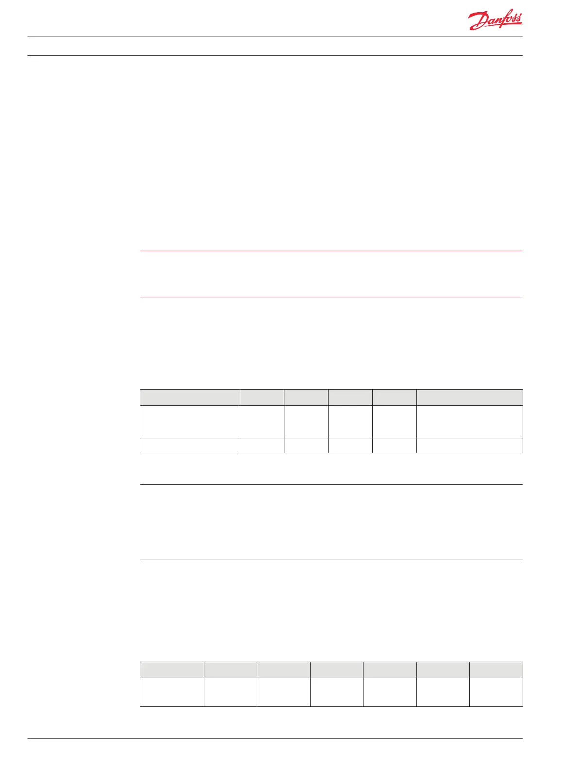
Description Units Minimum Maximum Nominal Comment
Resistance Ω 110 130 120 Minimum power dissipation
400 mW (assumes a short of 16
Vdc to CAN_H).
Inductance µH 1
CAN Bus Installation
Total bus impedance should be 60 Ω.
The CAN transceiver will be damaged by any voltage outside of allowable range, (-7 to +36 Vdc), even
with a very short pulse.
If using shielded cable, the shield must be grounded to the machine ground at one point only; preferably
at the mid-point of the CAN bus. Each PLUS+1 module CAN shield pin must be connected to the cable
shield.
Expansion Module CAN Bus Loading
System designers incorporating PLUS+1 expansion modules in their applications should be aware of
PLUS+1 CAN bus loading and controller memory usage during system design. Each expansion module is
associated with a PLUS+1 controller and uses part of the controller’s memory resources for inter-module
communications. The table below can be used to estimate system CAN bus loading and the memory
impact of I/O modules on their associated controller.
Estimated Usage of Memory and Communication Resources
Description IX012-010 IX024-010 OX012-010 OX024-010 IOX012-010 IOX024-20
Estimated
module bus load
(using default
4% 10% 11% 27% 11% 27%
Technical Information PLUS+1® Controller Family
Controller Area Network Specifications
20 520L0719 • Rev PB • Feb 2014