•
Switching any of the designated wake-up digital inputs (DIN) in the GUIDE application, to high
•
Cycling all input power to the controller
The following input pins may be designated as wake-up digital inputs:
•
DIN (C1p06, C1p07)
•
DIN/AIN (C1p14, C1p17 to C1p20, C1p24 to C1p27
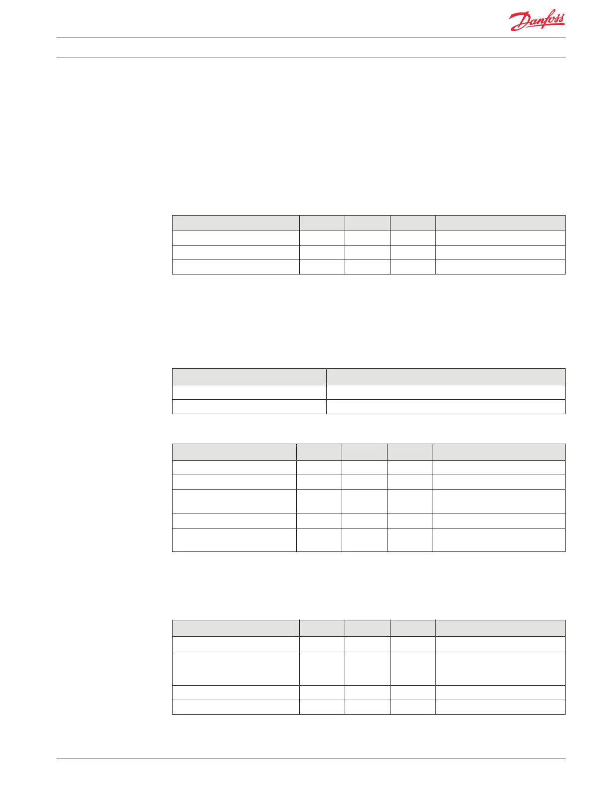
Specifications
Description Units Minimum Maximum Comment
Wake-up pin threshold Vdc 2 36 To wake up by cycling input power.
Wake-up pin threshold Vdc 4.5 36 To wake up by digital input.
Wake-up time delay mSec 250 500
Sensor Power Supply Ratings
PLUS+1 modules that support sensor inputs are provided with dedicated regulated sensor power supply
and ground pins. Refer to individual product data sheets for sensor power supply current ratings. The
sensor power is nominally 5 Vdc, unless otherwise noted on the product data sheet.
General
Description Comment
Short circuit to ground Output is not damaged and fault is detected.
Short circuit to battery + Output is not damaged and fault is detected.
Specifications (all modules except MC050-055/05B)
Description Units Minimum Maximum Comment
Output short circuit voltage Vdc 36
Output voltage Vdc 4.88 5.12
Output current mA Refer to individual data sheets for
sensor power supply ratings.
Output Load Capacitance µF 10
Hold up time after power loss m
s
5 15
MC050-055/05B controllers feature two additional levels of regulated power: 1.6 Vdc and 3.3 Vdc. The
PLUS+1 GUIDE application developer can detect open and short digital inputs, when these power
supplies are used in conjunction with DIN/AIN inputs.
Specifications (MC050-055/05B)
Description Units Minimum Maximum Comment
Output short circuit voltage Vdc 36
Output voltage, sensors Vdc 4.88 5.12 Sensor power supply drops below
minimum if controller power supply
is less than 9 Vdc.
Output voltage, DIN diagnostics Vdc 1.54 1.66 Nominal 1.6
Output voltage, DIN diagnostics Vdc 3.00 3.60 Nominal 3.3
Technical Information PLUS+1® Controller Family
Product Ratings
520L0719 • Rev PB • Feb 2014 23