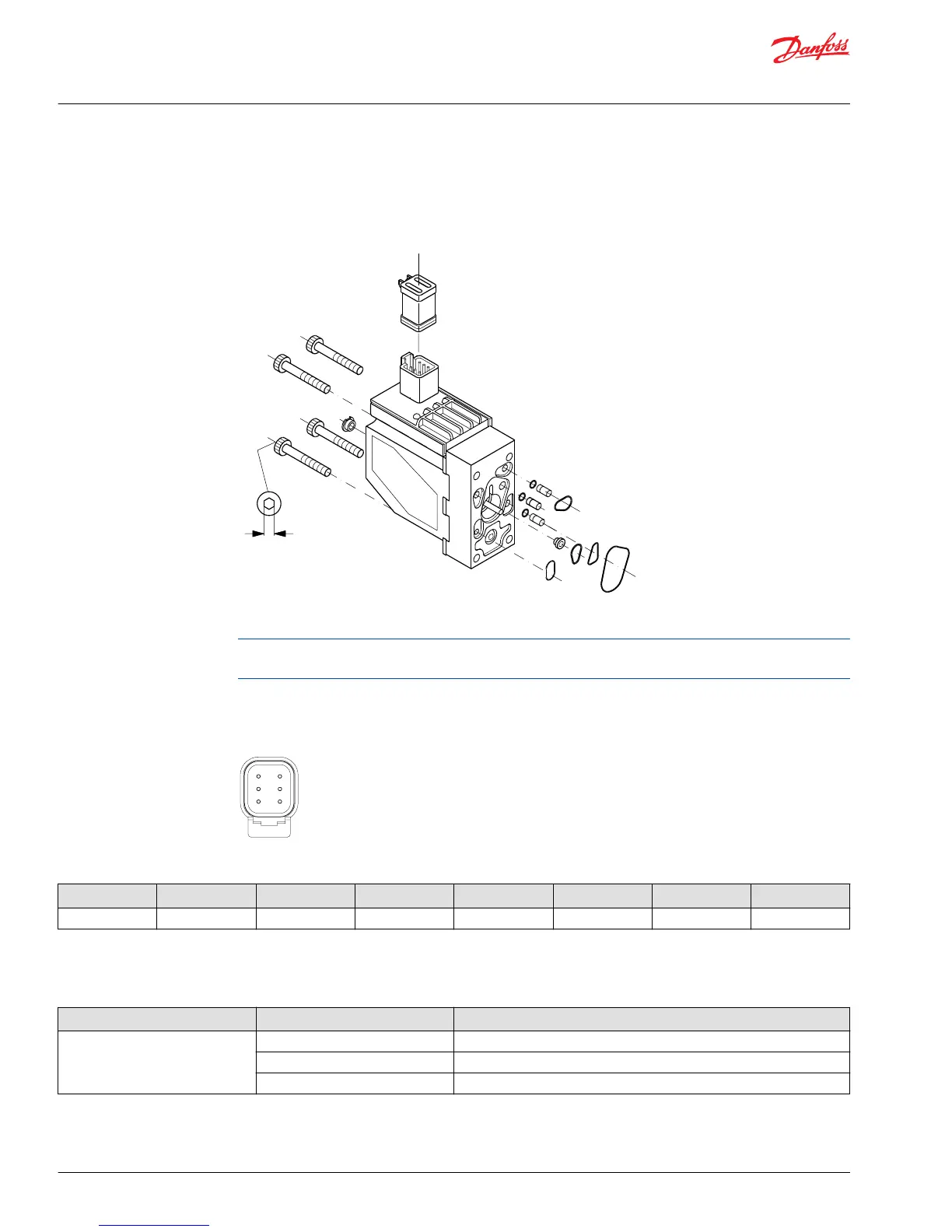
PVEP series 4 for PVG 32
Seals must be correctly set to successfully seal the connector.
PVEP/PVEP-F
5[0.20]
8±0.5 Nm
[70±4.4 lbf·in]
PVEP/PVEP-F
Be sure to protect the LVDT Pin and O-rings are in place during installation. Do not over torque.
The seal in the DEUTSCH connector and the use of 1.5 mm
2
lines in all connections are crucial for
correctly sealing the connector.
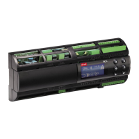
PVEP series 4 for PVG 32 pin layout
1x6 DEUTSCH
Pin layout
Type Connector Pin 1 Pin 2 Pin 3 Pin 4 Pin 5 Pin 6
PVEP 1x6 DEUTSCH PWM_A Error PWM_B No connection Not used Udc
PVEP series 4 for PVG 32 technical data
PVEP control specification
Description Type Value
Supply Voltage (UDC) Range 11 to 32 VDC
Max. ripple 5%
Max. 5 min 36 V
Service and Parts Manual
PVG 16/32/128/256
Installation
30 |
©
Danfoss | October 2018 AX284661889190en-000101