Do you have a question about the Danfoss MCX-RTU and is the answer not in the manual?
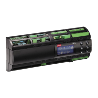
Overview of the MCX-RTU controller for commercial rooftop units and its integration.
Lists MCX-RTU controllers, expansion modules, and remote displays with their respective code numbers.
Details electrical specifications, power consumption, and Modbus communication cable requirements.
Lists EU Declaration of Conformity directives and UL Approval status for the product.
Describes DIN rail mounting and provides device dimensions for installation planning.
Shows the top-side connections for the MCX-RTU, including communication and analog/digital I/O.
Illustrates the bottom-side connections for power, digital inputs, and expansion modules.
Explains EIA485 cable requirements, repeaters, device addressing, and baud rate settings for Modbus.
Details the controller's operation in Cooling Mode, including stages, fan control, and free cooling.
Explains controller operation in Heating Mode, covering stages and fan control for various heating types.
Describes operation in Dehumidification Mode, including stages, fan control, and capacity modulation.
Details the CO2 Mode, its priority, and how it controls the damper based on CO2 levels.
Explains the DOAS Mode, its dependency on setup options, and use of outdoor sensors.
Illustrates the main status display, key indicators, and navigation controls for viewing system status.
Shows the current sensor values and lists the sensor abbreviations used in the system.
Displays broadcast sensor values received from the AK-SM 800, including RH, CO2, and load shed status.
Guides users on accessing main menu, login, parameters, setup options, and service settings for configuration.
Explains how to edit the controller's communication address through the service menu.
Details setup options for Fan Type, Fan Control, Cooling Stages, and Cooling Stage Types (RO/AO).
Covers setup options for Heat Reclaim, Aux Heat, Dehumidification Control, and Enthalpy Control.
Explains setup options for Damper Control Sensor, CO2 Option, and Free Cooling settings.
Details options for selecting Zone and Outdoor sensors (RH, CO2, Temp, etc.) and Broadcast sensor configuration.
Covers parameters like Invert Fan AO, Zone Control, Building Pressure Sensor, and Condenser Control.
Lists and explains general parameters such as Master Switch, Temperature Units, Reset options, and Night Setback.
Details parameters for selecting and broadcasting sensor values to other controllers.
Covers fan-related parameters like Off Delay, Proof Value, Min/Max Fan Speed, and PI Gain.
Details parameters for Cool Stages (Target, Pre/Post Delay, Range, Lockout) and Supply Air targets.
Lists parameters for Heat Reclaim stages, including Target, Pre/Post Delay, Range, and Lockout.
Details parameters for Aux Heat stages, including Target, Pre/Post Delay, Range, and Lockout.
Covers parameters for Dehumidification stages, including Target, Pre/Post Delay, Range, Lockout, and Reheat.
Details parameters for Damper configuration, including Min/Max Open, Air Target, and Lockout values.
Lists parameters for configuring alarms such as Fan Proof Delay and Zone High Temp Alarm.
Details parameters for Zone Low/High Temp alarms, Zone delays, and CO2 alarms and delays.
Lists parameters for monitoring daily cycles and runtimes for Fan, Cool, and Heat stages.
Explains overrides OV1-OV9 for Night Setback, Title24, Fan, Damper, Cooling, Heat Reclaim, Aux Heat, and Timeout.
Describes how to assign schedules to MCX-RTU via AK-SM 800, including On/Off and Eco/Com schedules.
Explains backing up and restoring MCX-RTU parameters to/from an SD card via the Service Menu.
Details using parameter C57 (Zone Control) to select sensor averaging (Single, Average, Low, High).
Lists data log points and explains enabling logging via parameters y36 and y37.
Guides on selecting sensors to broadcast using parameters y16-y20 and setup options C48-C52.
Explains setting up schedules on AK-SM 800 and selecting them for Night Setback (y26) and Title24 (y29).
Details setting up Load Shed parameters (y28) to control the unit based on broadcast values.
Steps to connect to the AK-SM 800 via Storeview Desktop or web browser for configuration.
Navigating to the HVAC Layout image within the AK-SM 800 configuration.
Using the HVAC layout wizard to define and configure the system, including network bus type.
Steps to enable the MODBUS-RS485 channel within the network settings of the wizard.
Scanning the network to discover controllers and displaying the list of HVAC controllers.
Adding, copying, or editing discovered offline controllers and viewing the final HVAC layout summary.
Confirming the HVAC layout setup completion status via a pop-up message.
Lists analog input types, their ranges (Min/Max), and sensor types (PT1000, 0-5V).
Details digital input types, their states (0/1), and contact types (N.O./N.C.).
Lists digital inputs from expansion modules, their states (0/1), and contact types (N.O./N.C.).
Lists analog output types, their ranges (0-10V, 1-5V), and availability status.
Details digital output types, their states (0/1), and contact types (N.O./N.C.).
| Brand | Danfoss |
|---|---|
| Model | MCX-RTU |
| Category | Control Unit |
| Language | English |