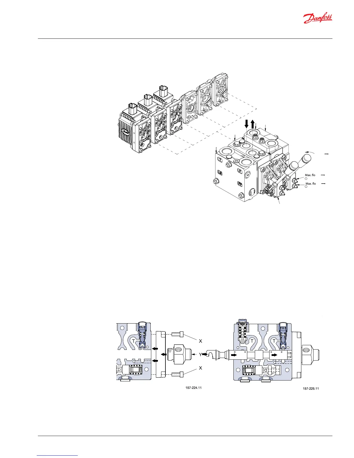
8. Assemble the actuators. The manual cover PVMD or the remote hydraulic end cover must be installed
with the arrow pointing upwards towards the “A/B” port.
The PVE’s must be installed with the connectors pointing upwards towards the “A/B” port. The torque
for the four (4) mounting screws is 0.8 + 0/-0.5 N•m [70 +0/-4.5 in. lbs.] using a 5 mm hex drive.
Common to all types of PVE’s is a small nylon filter in the “P” channel, under the O-ring. Insure that the
transducer stem on the PVE’s with closed loop feedback interfaces with the end of the PVBS without
any restrictions.
New and unused PVE units can be mounted without neutral adjustment to the LVDT transducer. If an
adjustment is required, contact the service department.
For control options with mechanical detent (PVMR) or mechanical float (PVMF) function, please follow
instructions in the previous section describing assembly of the PVMD or PVH remote with reference
to the below pictures.
Assembly of the actuators
Service Manual
PVG 16 and 32 Service Assembly/Disassembly Guide
Assembly instructions
©
Danfoss | November 2017 L1104530 | AX00000133en-US0106 | 19