1.2 Purpose of the Manual
This manual provides detailed information for the instal-
lation and start up of the frequency converter.
Chapter 3 Installation provides requirements for mechanical
and electrical installation, including:
•
Input
•
Motor
•
Control wiring
•
Serial communications wiring
•
Control terminal functions
VLT
®
is a registered trademark.
1.3 Product Overview
A frequency converter is an electronic motor controller
that converts DC into a variable AC waveform output. The
frequency and voltage of the output are regulated to
control the motor speed or torque. The frequency
converter can vary the speed of the motor in response to
remote commands from external controllers.
The frequency converter offers many control, monitoring
and efficiency functions such as
•
monitoring the system and motor status
•
Issuing warnings or alarms for fault conditions
•
starting and stopping the motor
•
optimising energy efficiency
Operation and monitoring functions are available as status
indications to an outside control system or serial communi-
cation network.
1.4
Internal Controller Functions
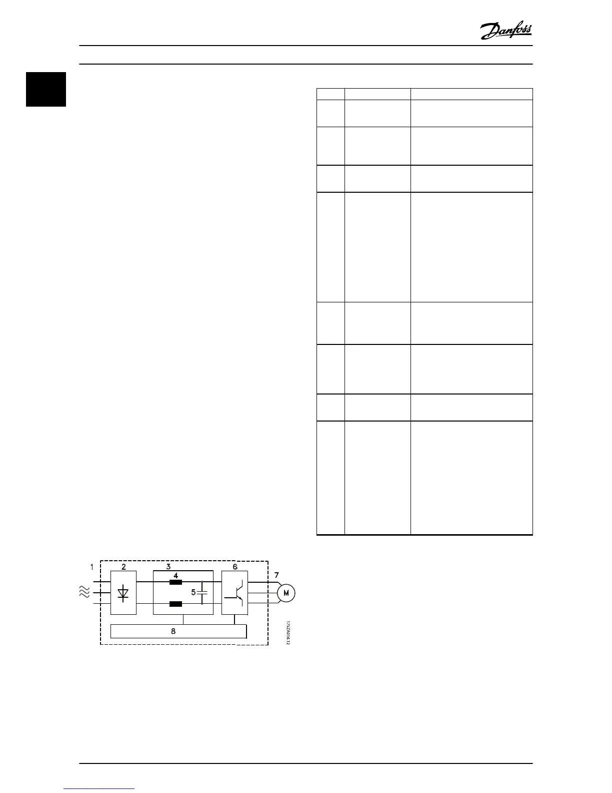
Illustration 1.3 is a block diagram of the frequency
converter's internal components.
Illustration 1.3 Frequency Converter Block Diagram
Area Title Functions
1 Mains input
•
3-phase AC mains supply to the
frequency converter
2 Rectifier
•
The rectifier bridge converts the
AC input to DC current to
supply inverter power.
3 DC-bus
•
Intermediate DC-bus circuit
handles the DC current.
4 DC reactors
•
Filter the intermediate DC circuit
voltage.
•
Prove line transient protection.
•
Reduce RMS current.
•
Raise the power factor reflected
back to the line.
•
Reduce harmonics on the AC
input.
5 Capacitor bank
•
Stores the DC power.
•
Provides ride-through protection
for short power losses.
6 Inverter
•
Converts the DC into a
controlled PWM AC waveform
for a controlled variable output
to the motor.
7 Output to motor
•
Regulated 3-phase output
power to the motor
8 Control circuitry
•
Input power, internal processing,
output, and motor current are
monitored to provide efficient
operation and control.
•
User interface and external
commands are monitored and
performed.
•
Status output and control can
be provided.
Table 1.2 Legend to Illustration 1.3
Introduction Danfoss Turbocor
4 Danfoss A/S © 01/2015 All rights reserved. MG35Q202
1
1