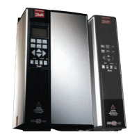
VLT® 5000 Crane
Relay Outputs
Number of programmable relay outputs 2
Terminal numbers, control cards 4-5 NO
Max. terminal load (AC) on 4-5 control card 50 V AC, 1A, 60 VA
Max. terminal load (DC) on 4-5, control card 75 V DC, 1A, 30W
Max. terminal load (DC) on 4-5, control card
UL applications
cUL applications
30 V AC, 1A
1A, 42.5 V DC
Terminal numbers, power card 1-3 NC, 1-2 NO
Max. terminal load (AC) on 1-3, 1-2, power card 240 V AC, 2A, 60 VA
Max. terminal load on 1-3, 1-2, power card 50 V DC, 2 A
Min. terminal load on 1-3, 1-2, power card 24 V AC/24 V DC, 10/100mA
Brake Resistor Terminal
Terminal numbers 81, 82
Cable Lenghts and Cross-Sections
Max. motor cable length, screened cable 25m
Max. brake cable length, screened cable 5m
Max. cable cross-section for control cables 0.75mm
2
/AWG
Max. cross-section for serial communication 0.75mm
2
/AWG
NOTE: Max. cable cross-section for motor and brake, see Installation
Accuracy of Display Readout (Parameters 009 - 012)
Motor Current [6] 0 - 140% load Max error: 2% of rated output current
Torque % [7] -100 - 140% load Max error: 5% of rated motor size
Output [8], power HP [9] 0 - 90% load Max error: 5% of rated output
Control Caracteristics
Frequency range 0-160 Hz
Resolution on output frequency ± 0.003 Hz
System response time* <5msec
Speed, control range 1:1000 of synchro speed
Speed, accuracy
<1500 rpm
>1500 rpm
Max error:
±1.5rpm
0.1% of actual speed
Torque control accuracy (Speed feedback) Max error: ± 5% of rated torque
NOTE: All control caracteristics are based on 4-pole asynchronous motors
*The system response time is the time passing
from the input receives a signal to a reaction
occurs on the VLT output.
MG.50.N4.02 - VLT is a registered Danfoss trademark
18

 Loading...


