EasyManua.ls Logo

Danfoss VLT 8000 AQUA series User Manual

Danfoss VLT 8000 AQUA series
206 pages
To Next Page IconTo Next Page
To Previous Page IconTo Previous Page
Page #153 background imageLoading...
Page #153 background image
VLT
®
8000 AQUA
Programming
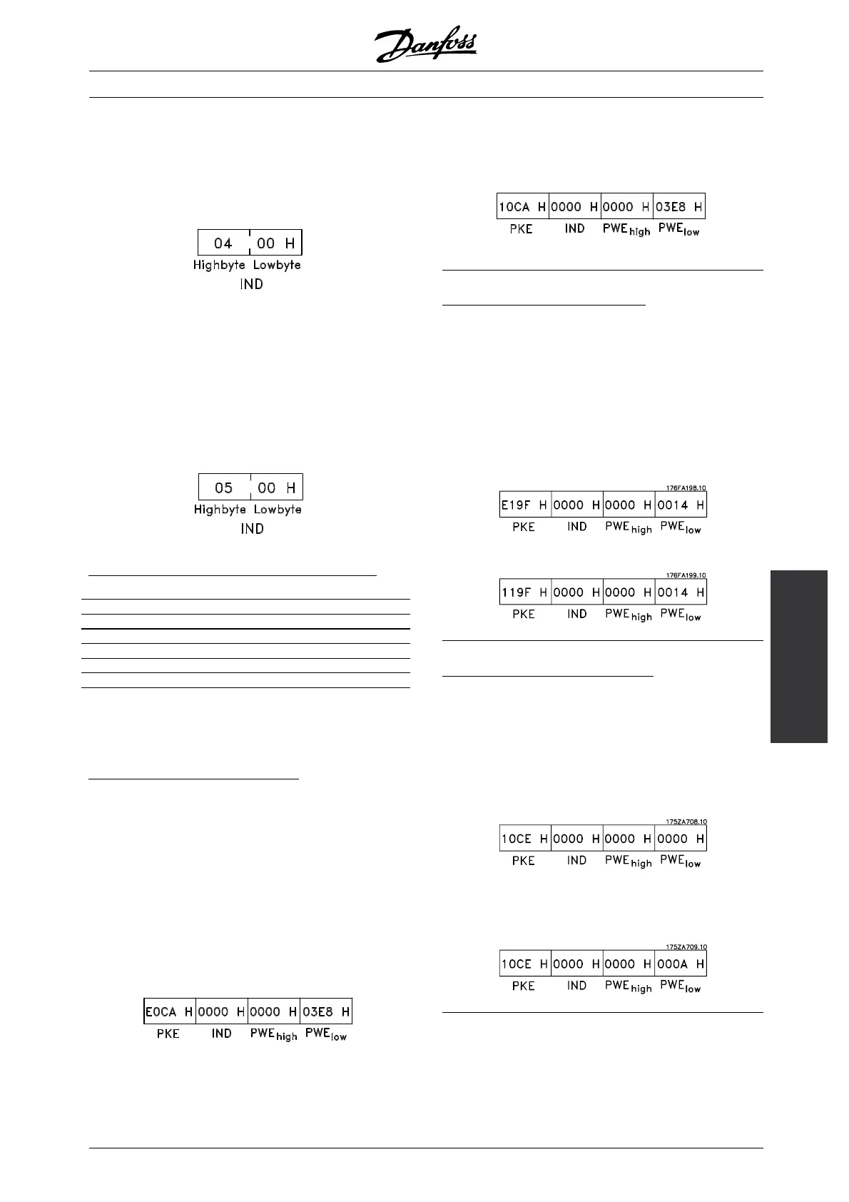
The index character is used to indicate whether
the command in question is a read or write
command. For a read command, the index
must have the following format:
VLT 8000 AQUA has two parameters for which a text
can be written: parameters 533 and 534 Display text,
see the description of these under the parameter
description. In order to write a text via the PWE block,
the parameter command (AK) must be set to F Hex.
For a write command, the index must have
the following format:
Data types supported by the frequency converter
Datatype Description
3Integer16
4Integer32
5 Unsigned 8
6 Unsigned 16
7 Unsigned 32
9Textstring
Unsigned means there is no sign included
in the telegram.
E
xample - Write a parameter value:
Parameter 202 Output frequency high limit, f
MAX
is to
be changed to 100 Hz. This value must be remember
after a power failure, so it is written in EEPROM.
PKE = E0CA Hex - Write to parameter 202
Output frequency high limit, f
MAX
IND = 0000 Hex
PWE
HIGH
= 0000 Hex
PWE
LOW
03E8 Hex - Data value 1000,
correspondingto100Hz,see
Conversion.
The reply from the slave to the master will be:
Example - Choice of a data value:
kW [20] is to be selected in parameter 415 Process
units. This value must be remembered after a power
failure, so it is written in EEPROM.
PKE = E19F Hex - Write to parameter 415
Process units
IND = 0000 Hex
PWE
HIGH
= 0000 Hex
PWE
LOW
0014 Hex - Choose data choice kW
[20]
Svaret fra slaven til masteren vil være:
Example - Read a parameter value:
The value in parameter 206 Ramp-up time is required.
The master sends the following inquiry:
PKE = 10CE Hex - read parameter 206
Ramp-up time
IND = 0000 Hex
PWE
HIGH
=0000Hex
PWE
LOW
0000 Hex
If the parameter value in parameter 206 Ramp-up
time is 10 seconds, the reply from the slave to
the master will be as follows:
MG.83.A2.02 - VLT is a registered Danfoss trademark
153

Table of Contents

Question and Answer IconNeed help?

Do you have a question about the Danfoss VLT 8000 AQUA series and is the answer not in the manual?

Danfoss VLT 8000 AQUA series Specifications

General IconGeneral
CategoryDC Drives
Storage Temperature-25 to 70 °C
Input Voltage380V to 500V AC
EnclosureIP20, IP21, IP55
Communication ProtocolsProfibus DP
ApplicationWater and Wastewater applications
Protection FeaturesOverload, Overvoltage, Undervoltage, Short Circuit
Relative HumidityUp to 95%, non-condensing
AltitudeUp to 1000 m
Ambient Temperature-10 to 50°C (depending on model and derating)

Summary

Introduction

Safety regulations

Essential guidelines for safe operation, installation, and maintenance of the frequency converter.

Installation

General technical data

Comprehensive specifications and electrical characteristics of the VLT 8000 AQUA frequency converter.

Mechanical installation

Guidelines and procedures for physically installing the frequency converter unit correctly.

EMC-correct electrical installation

Best practices for wiring and grounding to ensure electromagnetic compatibility.

Programming

Quick Menu

Provides access to the 12 most important setup parameters for quick and efficient drive configuration.

Load and motor 100-124

Parameters for configuring regulation, torque characteristics, and motor nameplate data.

Automatic motor adaptation, AMA

Details on the automated process for measuring motor parameters for optimal performance.

Service functions 600-631

Functions for reading operating data, fault logs, and nameplate information for diagnostics.

All about VLT 8000 AQUA

List of warnings and alarms

Comprehensive list of fault codes, descriptions, and their impact on frequency converter operation.

Related product manuals