31-22 Above level threshold
Range: Function:
#
*
[ -2500 - 2500 Pa] Enter the above-level threshold.
31-23 On Delay Time
Range: Function:
60 s
*
[0 - 3600 s] Enter the on delay time.
31-24 Reset Delay Time
Range: Function:
9999 s
*
[0 - 9999 s] Enter the reset delay time.
31-25 Pressure lter time constant
Range: Function:
1 s
*
[0.01 - 60 s] Enter the pressure lter time constant. A
longer value make the pressure signal more
stable but less dynamic. A shorter value
allows to eliminate signal spikes and keep
control more dynamic.
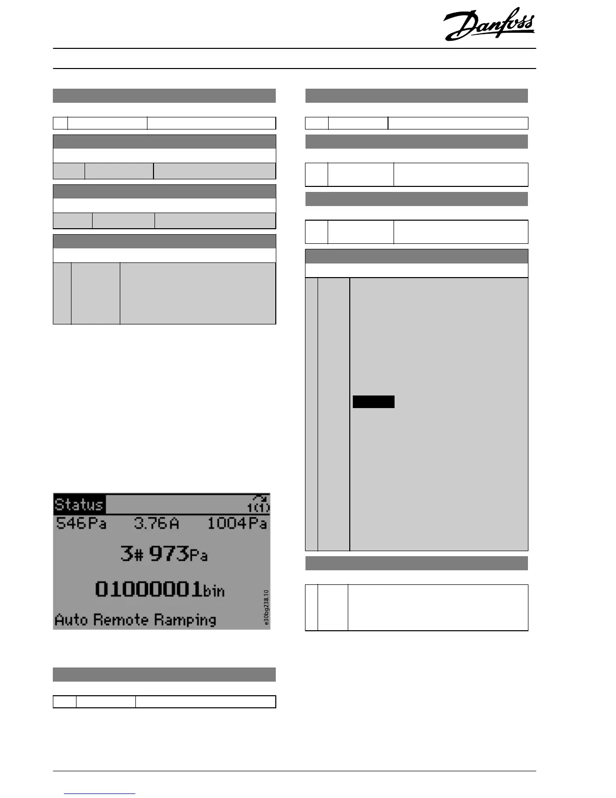
31-2* Readouts
Parameters in this group contain the actual pressure levels and
the status information. The LCP can be congured to show the
values of these parameters in
dierent
display lines. The
toggle function allows to show multiple pressure signals in the
same LCP line. The number is followed by the hash sign (#).
See Illustration 1.9.
Use parameter 0-20 Display Line 1.1 Small to
parameter 0-24 Display Line 3 Large to congure the LCP to
show
dierent
pressure values.
Illustration 1.9 Pressure Sensor Data on the LCP
31-26 Pressure Sensor 1
Range: Function:
0 Pa
*
[-500 - 500 Pa] Shows the readout of pressure sensor 1.
31-27 Pressure Sensor 2
Range: Function:
0 Pa
*
[-500 - 500 Pa] Shows the readout of pressure sensor 2.
31-28 Pressure Sensor 3
Range: Function:
0 Pa
*
[-1000 - 1000 Pa] Shows the readout of pressure sensor
3.
31-29 Pressure Sensor 4
Range: Function:
0 Pa
*
[-2500 - 2500 Pa] Shows the readout of pressure sensor
4.
31-30 Press Sens Cmp State
Range: Function:
0
*
[0 -
255]
Shows the pressure sensor state. The state is an 8-
digit binary value, where 1 indicates an active status
and 0 indicates an inactive status. Reading from
right to left, the rst 4 digits indicate the alarms for
the below-level threshold, and the last 4 digits the
alarms for the above-level threshold. For instance,
counting from right to left, sensor 1 for the below-
level threshold is at position 1, and sensor 1 for the
above-level threshold is at position 5. See
Illustration 1.9.
NOTICE
When using this parameter in the smart logic
controller, the output status signal for the
below-level threshold and for the above-level
threshold is the same for a specic sensor.
For example, in the following cases the
output status signal is the same:
•
The below-level threshold for sensor
1 is active.
•
The above-level threshold for sensor
1 is active.
31-31 Press Sens toggle
Range: Function:
[0 - 4] Shows the pressure values on all sensors. The
readout switches between sensors in a loop, going
from sensor 1 to sensor 4. The sensor number is
followed by a hash sign, see Illustration 1.9.
Installation Instructions
Pressure Transmitter Unit PTU 025
VLT
®
HVAC Drive FC 102
8
Danfoss A/S © 12/2017 All rights reserved. MI08A102
 Loading...


