Danfoss code Typecode
Ω
L±2
mm
L±0.08 in L1±2 mm L1±0.04 in
Weight [kg]
175U3179 MCE101A5R70P5K50E65TAW 5,7 760 29.92 730 28.74 33.5
175U3473 MCE101A15R5P4K20E65TAW 15,5 660 25.95 630 24.8 30
175U3475 MCE101A13R5P5K50E65TAW 13,5 760 29.92 730 28.74 33.5
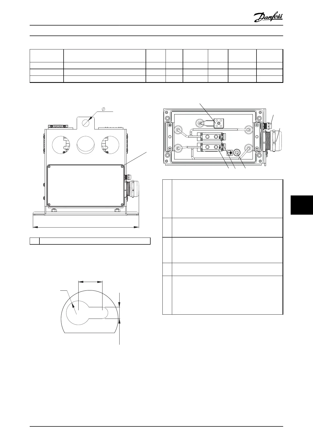
Table 9.32 Mechanical Dimension
130BD287.10
[11.85]
301
[0.79]
20
1
1 Torque 1–1.4 Nm (8.86-12.34 lb-in)
Illustration 9.86 IP65, End View, Connection Box
130BD291.10
[0.71]
18
[0.33]
8.5
[0.35]
R9
Illustration 9.87 Mounting Hole
1 Temperature switch connection:
Marked: T1 /T2
IEC: 0.2–4 mm
2
/500 V
UL: AWG 24-12/300 V
Wire stripping: 8 mm (0.31 in)
Torque: 0.7 Nm (6.2 lb-in)
2 For temperature switch cable:
Clamping range: 3.5–7.0 mm (0.14–0.28 in)
Size Wrench (SW): 16 mm (0.63 in)
3 For resistor cable:
Cable gland with internal connection for braid
Clamping range: 19–28 mm (0.74–1.1 in)
Size Wrench (SW): 45 mm (1.78)
4 PE: M8
Torque 4.5-5-5 Nm (39.83–48.68 lb-in)
5 Resistor connection:
Marked RB1/RB2
IEC: Cu 2.5–50 mm
2
, AI: 6-50 mm
2
/750 V
UL: AWG 6-1/0/600 V
Wire stripping: 23 mm (0.9 in)
Torque: 10 Nm (88.51 lb-in)
Illustration 9.88 Connection Box
Specifications Design Guide
MG90O202 Danfoss A/S © Rev. 05/2014 All rights reserved. 123
9 9

 Loading...

