4 System Integration
4.1 Brake Resistor Calculation
To ensure the optimal selection of brake resistor for a
given application, its inertia and braking profile
calculations are required.
This chapter explains the calculations required to obtain
values for optimal selection of brake resistor for a given
application.
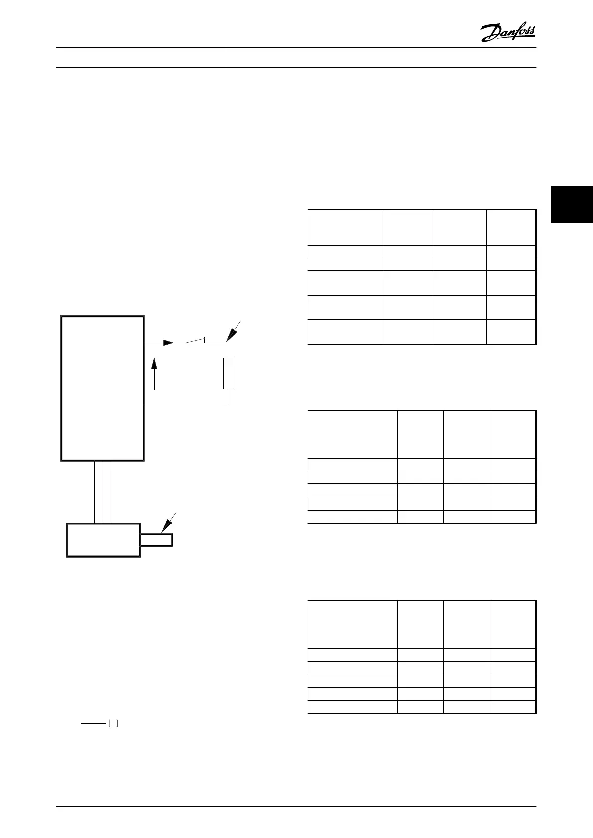
4.1.1 Brake Set-up
The following sections use expressions and abbreviations
related to the brake set-up in Illustration 4.1.
P
peak,mec.
175ZA096.14
VLT
U
DC
I
termo
P
peak
P
avg
R
br
P
b, max
P
motor
η
INV
= 0.98
η
motor
= 0.9
Illustration 4.1 Brake Set-up
4.1.2
Calculation of Brake Resistor
Resistance
To prevent the frequency converter from cutting out for
protection when the motor brakes, select resistor values on
the basis of the peak braking power and the intermediate
circuit voltage:
R
br
=
Udc
2
P
peak
Ω
The brake resistor performance depends on the DC-link
voltage (U
dc
).
U
dc
is the voltage, where the brake is activated. The FC-
series brake function is settled depending on the mains
supply.
DC-link Voltage (U
dc
), FC 51
Size [V] Brake active
[V]
Warning
before cut
out [V]
Cut out
(trip) [V]
FC 51 1x200-240 390 410 410
FC 51 3x200-240 390 410 410
FC 51 3x380-480,
1.5-4.0 kW
770 800 800
FC 51 3x380-480,
5.5-15 kW
705-770
1)
800 800
FC 51 3x380-480,
18.5-22 kW
770 800 800
Table 4.1 DC-link Voltage (U
dc
), FC 51
1) Adjustable with 2-14 Brake Voltage Reduce
DC-link Voltage (U
dc
), FC 102
Size [V]
Brake
active
[V DC]
High
voltage
warning
[V DC]
Over
voltage
alarm
[V DC]
FC 102 3x200-240 390 405 410
FC 102 3x380-480 778 810 820
FC 102 3x525-600
1)
943 965 975
FC 102 3x525-600
2)
1099 1109 1130
FC 102 3x525-690 1099 1109 1130
Table 4.2 DC-link Voltage (U
dc
), FC 102
1) Enclosure types A, B, C
2) Enclosure types D, E, F
DC-link Voltage (U
dc
), FC 202
Size [V]
Brake
active
[V DC]
High
voltage
warning
[V DC]
Over
voltage
alarm
[V DC]
FC 202 3x200-240 390 405 410
FC 202 3x380-480 778 810 820
FC 202 3x525-600
1)
943 965 975
FC 202 3x525-600
2)
1099 1109 1130
FC 202 3x525-690 1099 1109 1130
Table 4.3 DC-link Voltage (U
dc
), FC 202
1) Enclosure types A, B, C
2) Enclosure types D, E, F
System Integration
Design Guide
MG90O202 Danfoss A/S © Rev. 05/2014 All rights reserved. 15
4 4

 Loading...

