130BD305.10
[4.02]
102
[0.79]
20
1
[5.84]
148.3
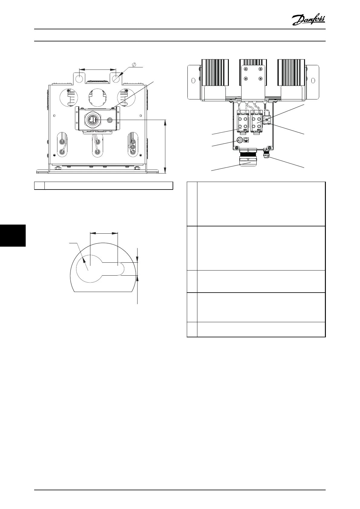
1 Torque 1–1.4 Nm (8.86–12.34 in)
Illustration 9.92 IP21, End View, Connection Box
130BD309.10
[0.71]
18
[0.33]
8.5
[0.35]
R9
Illustration 9.93 Mounting Hole
1 Resistor connection:
Marked RB1/RB2 ENSTO KE66
EIC: Cu 2.5-50 mm
2
, AI 6-50 mm
2
/750 V
UL: AWG 6-1/0 / 600 V
Wire stripping: 23 mm (0.9 in)
Torque: 10 Nm (90 lb-in)
2 Temperature switch connection:
Marked: T1/T2 PHOENIX G5/2
IEC: 0.2-4 mm
2
/500 V
UL: AWG 28-10/300 V
Wire stripping: 8 mm (0.31 in)
Torque: 0.7 Nm (6.2 lb-in)
3 For temperature switch cable:
Clamping Range: 3.5-7.0 mm (0.14–0.28 in)
Size Wrench (SW): 16 mm (0.63 in)
4 For resistor cable:
Cable gland with internal connection for braid
Clamping Range: 19-28 mm (0.74–1.1 in)
Size Wrench (SW): 45 mm (1.78 in)
5 PE: M8
Torque: 5–5.5 Nm (44.28–48.71 lb-in)
Illustration 9.94 Connection Box
Specifications Design Guide
126 Danfoss A/S © Rev. 05/2014 All rights reserved. MG90O202
99

 Loading...

