Procedure
1. Apply a start signal on terminal 18.
2. Connect terminals 12, 27, and terminal 53, 54, or 55.
3. Set the functions of digital inputs 18, 19, and 27 in parameter 5-00 Digital Input Mode (PNP is default value).
4. Set the function of digital input 29 in parameter 5-03 Digital Input 29 Mode (PNP is default value).
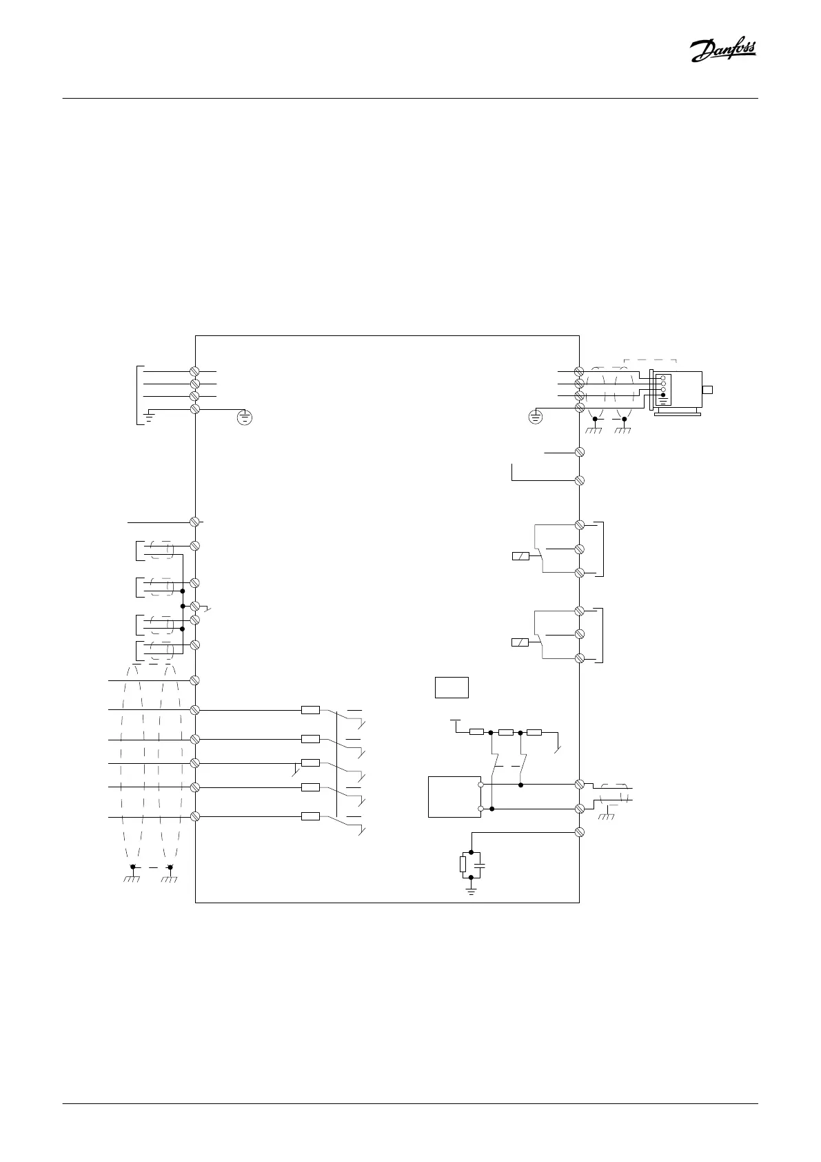
3.2.7 Electrical Wiring
+10 V DC
0-10 V DC-
0-10 V DC-
50 (+10 V OUT)
54 (A IN)
53 (A IN)
55 (COM A IN/OUT)
42 0/4-20 mA A OUT / D OUT
45 0/4-20 mA A OUT / D OUT
18 (D IN)
19 (D IN)
27 (D IN/OUT)
29 (D IN/OUT)
12 (+24 V OUT)
24 V (NPN)
20 (COM D IN)
O V (PNP)
24 V (NPN)
O V (PNP)
24 V (NPN)
O V (PNP)
24 V (NPN)
O V (PNP)
Bus ter.
Bus ter.
RS485
Interface
RS485
(N RS485) 69
(P RS485) 68
(Com RS485 ) 61
(PNP)-Source
(NPN)-Sink
ON=Terminated
OFF=Unterminated
ON
1 2
240 V AC 3 A
Not present on all power sizes
Do not connect shield to 61
01
02
03
relay 1
relay 2
UDC+
UDC-
Motor
U
V
W
e30bd467.12
06
05
04
240 V AC 3 A
Illustration 12: Basic Wiring Schematic Drawing
Installation
Operating Guide | VLT® Compressor Drive CDS 803
AQ321748767627en-000101 / 130R0570
22 | Danfoss A/S © 2019.12

 Loading...


