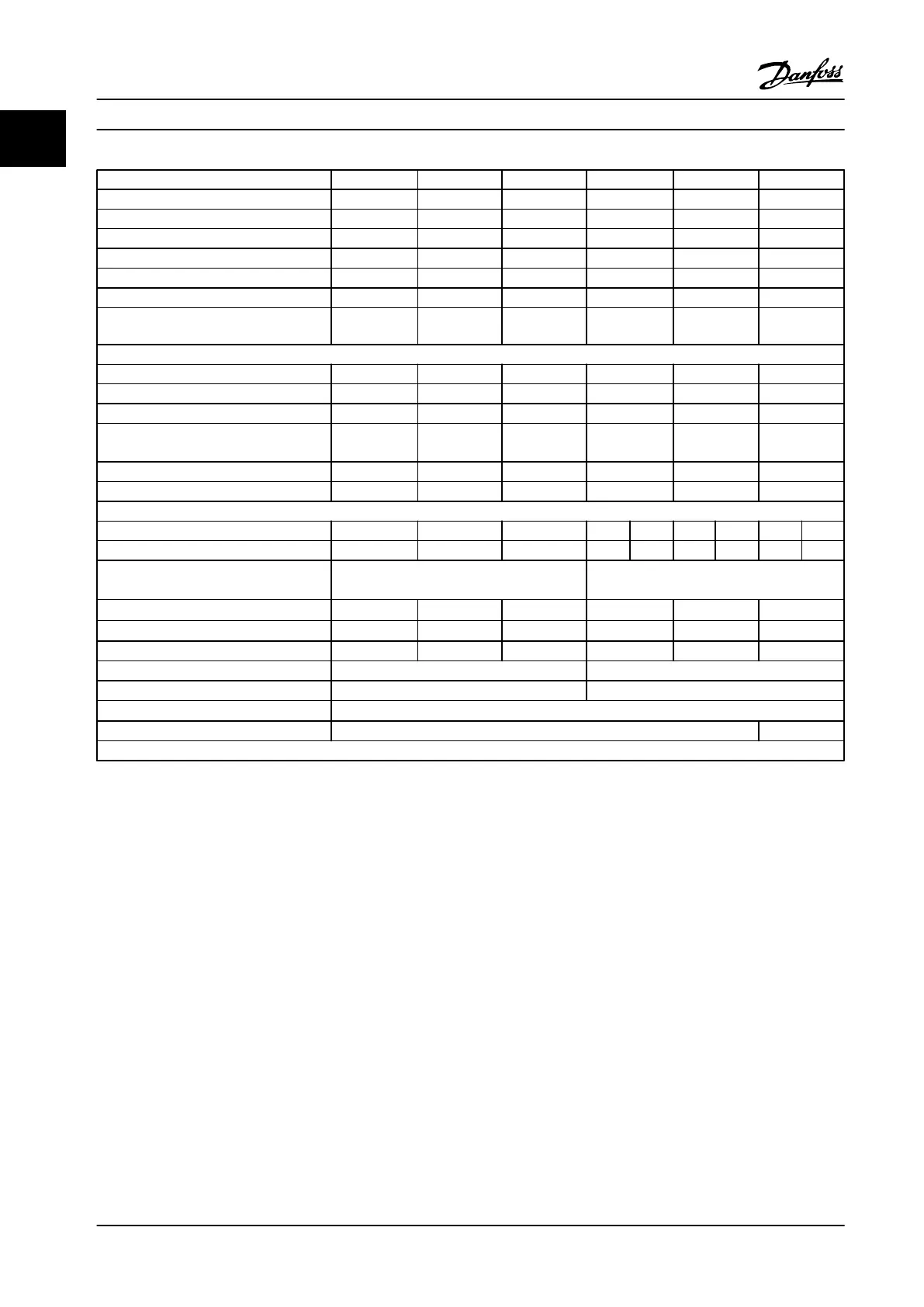
FC 102, FC 202, and FC 103 N110 N132 N160 N200 N250 N315
High/Normal Load* NO NO NO NO NO NO
Typical Shaft output at 400 V [kW] 110 132 160 200 250 315
Typical Shaft output at 460 V [hp] 150 200 250 300 350 450
Typical Shaft Output at 480 V [kW] 132 160 200 250 315 355
Enclosure IP21 D1h D1h D1h D2h D2h D2h
Enclosure IP54 D1h D1h D1h D2h D2h D2h
D3h D3h D3h D4h D4h D4h
Output current
Continuous (at 400 V) [A] 212 260 315 395 480 588
Intermittent (60 s overload) (at 400 V) [A] 233 286 347 435 528 647
Continuous (at 460/500 V) [A] 190 240 302 361 443 535
Intermittent (60 s overload) (at 460/500 V)
[kVA]
209 264 332 397 487 588
Continuous kVA (at 400 V) [kVA] 147 180 218 274 333 407
Continuous kVA (at 460 V) [kVA] 151 191 241 288 353 426
Max. input current
Continuous (at 400 V) [A] 204 251 304 381 381 463 463 567
Continuous (at 460/500 V) [A] 183 231 291 348 348 427 427 516
Max. cable size: line power, motor, brake
and load share [mm
2
] (AWG
2)
)
5)
2x95
(2x3/0)
2x185
(2x350)
Max. external electrical fuses [A]
1)
315 350 400 550 630 800
Estimated power loss at 400 V [W]
4)
2555 2949 3764 4109 5129 6663
Estimated power loss at 460 V [W] 2257 2719 3622 3561 4558 5703
Weight, enclosure IP21, IP54 kg (lbs) 62 (135) 125 (275)
Weight, enclosure IP20 kg (lbs) 62 (135) 125 (275)
Efficiency
4)
0.98
Output frequency 0–800 Hz 0–600 Hz
*Normal overload = 110% current for 60 s
Table 1.12 Line Power Supply 3x380–480 V AC
1) For type of fuse, see the Instruction Manual.
2) American Wire Gauge
3) Measured using 16.5 ft [5 m] shielded motor cables at rated load and rated frequency.
4) The typical power loss is at nominal load conditions and within ± 15% (depending on various voltage and cable
conditions).
5) Field wiring terminals on FC 102 N132, N160, and N315 models are not intended to receive conductors one size
larger.
Values are based on a typical motor efficiency (eff2/eff3 border line). Motors with lower efficiency add to the
power loss in the adjustable frequency drive and those with higher efficiency decrease it.
The losses are based on the default switching frequency. The losses increase significantly at higher switching
frequencies. LCP and typical control card power consumption values are included. Further options and customer
load may add up to 30 W to the losses. (Though typically, only 4 W extra for a fully loaded control card, or options
for slot A or slot B, each).
Introduction
Service Manual
14 Danfoss A/S © Rev. 2014-02-10 All rights reserved. MG94A222
1
1
 Loading...


