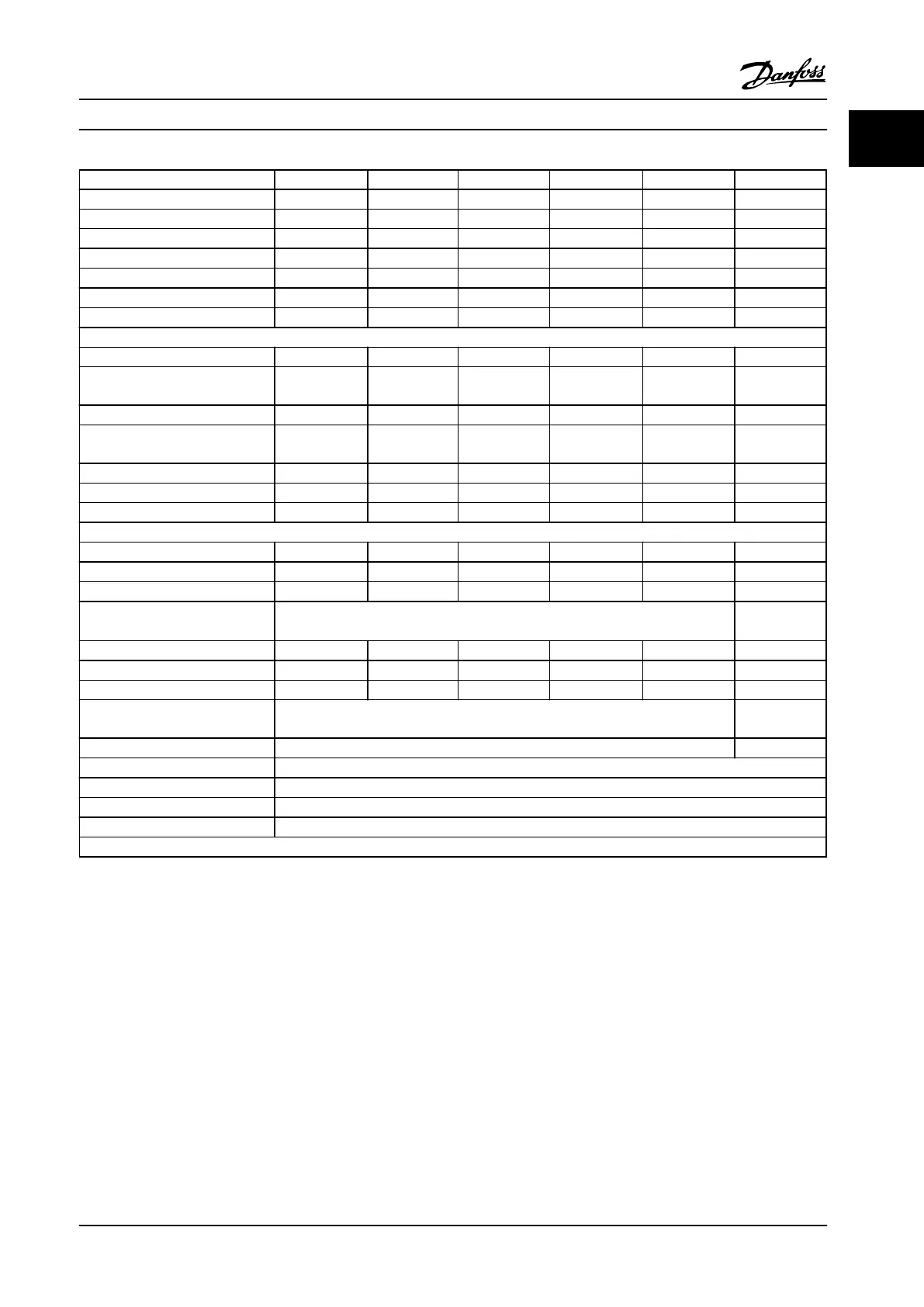
FC 102, FC 202 and FC103 N75K N90K N110 N132 N160 N200
Normal Load* NO NO NO NO NO NO
Typical Shaft output at 550 V [kW] 55 75 90 110 132 160
Typical Shaft output at 575 V [hp] 75 100 125 150 200 250
Typical Shaft output at 690 V [kW] 75 90 110 132 160 200
Enclosure IP21 D1h D1h D1h D1h D1h D2h
Enclosure IP54 D1h D1h D1h D1h D1h D2h
Enclosure IP20 D3h D3h D3h D3h D3h D4h
Output current
Continuous (at 550 V) [A] 90 113 137 162 201 253
Intermittent (60 s overload)
(at 550 V) [A]
99 124 151 178 221 278
Continuous (at 575/690 V) [A] 86 108 131 155 192 242
Intermittent (60 s overload)
(at 575/690 V) [kVA]
95 119 144 171 211 266
Continuous kVA (at 550 V) [kVA] 86 108 131 154 191 241
Continuous kVA (at 575 V) [kVA] 86 108 130 154 191 241
Continuous kVA (at 690 V) [kVA] 103 129 157 185 229 289
Max. input current
Continuous (at 550 V) [A] 89 110 130 158 198 245
Continuous (at 575 V) [A] 85 106 124 151 189 234
Continuous (at 690 V) [A] 87 109 128 155 197 240
Max. cable size: line power, motor,
brake and load share [mm
2
] (AWG)
2x95 (2x3/0)
2x185
(2x350 mcm)
Max. external electrical fuses [A] 160 315 315 315 350 350
Estimated power loss at 575 V [W] 1161 1426 1739 2099 2646 3071
Estimated power loss at 690 V [W] 1203 1476 1796 2165 2738 3172
Weight, enclosure IP21, IP54 kg
(lbs)
62 (135) 125 (275)
Weight, enclosure IP20 kg (lbs) 62 (135) 125 (275)
Efficiency 0.98
Output frequency 0–590 Hz
Heatsink overtemp. trip 230°F [110°C]
Power card ambient trip 167°F [75°C]
*Normal overload=110% current for 60 s
Table 1.15 Line Power Supply 3 x 525–690 V AC
Introduction Service Manual
MG94A222 Danfoss A/S © Rev. 2014-02-10 All rights reserved. 17
1
1
 Loading...


