VLT
®
FCD Series
■ Safety functions in connection with installation
When a brake resistor is installed, the best possible
endeavours should be made to avoid overloads, as
the heat generating from a brake resistor may in-
volve a fire risk.
NB!:
The brake resistor
should be fitted to a nonflammable material.
For protection of the installation, a thermal relay is
fitted that cuts out the frequency converter if the
brake current is too high. Danfoss’ 40% brake resis-
tors contain a KLIXON switch. Flat pack resistors
are self-protecting.
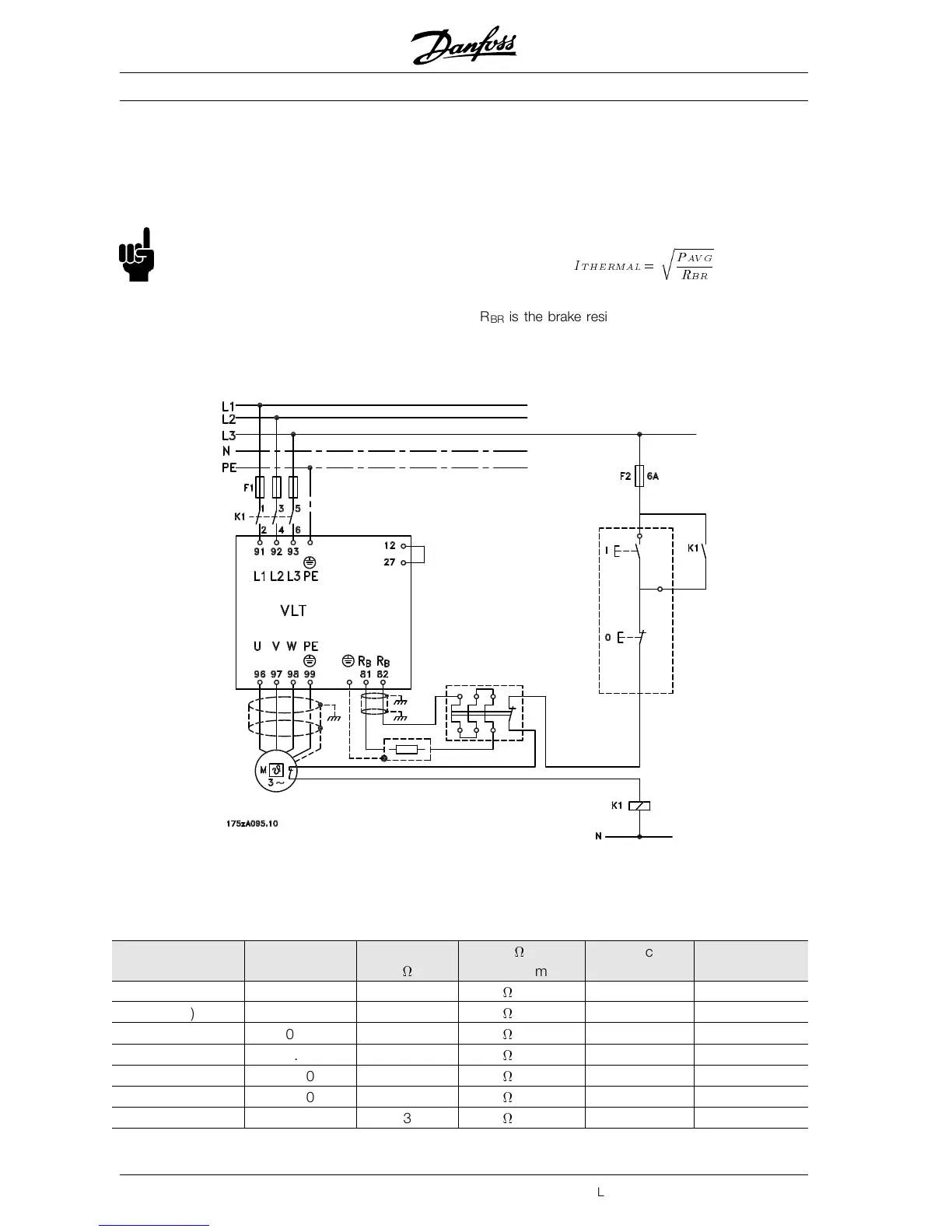
The brake current setting on the thermal relay is cal-
culated as follows:
I
T HERMAL
=
r
P
AV G
R
BR
R
BR
is the brake resistor value at any given time.
The drawing shows an installation with a thermal re-
lay.
■ Ordering numbers for brake resistors
Flatpack brake resistors IP 54
Type P
motor
[kW]
R
MIN
[
]
Size [
] / [W]
per item
Duty cycle % Order no.
175Uxxxx
303 (400 V) 0.37 747 830
/ 100 W 20 1000
305 (400 V) 0.55 747 830
/ 100 W 20 1000
307 (400 V) 0.75 558 620
/ 100 W 14 1001
311 (400 V) 1.10 387 430
/ 100 W 8 1002
315 (400 V) 1.50 297 310
/ 200 W 16 0984
322 (400 V) 2.20 198 210
/ 200 W 9 0987
330 (400 V)
3.00 135 150
/ 200 W 5.5 0989
MG.04.A1.02 - VLT is a registered Danfoss trade mark
20
 Loading...


