NOTICE!
The power cables are heavy and dicult to bend. Give thought to the optimum position of the adjustable frequency
drive for ensuring easy installation of the cables.
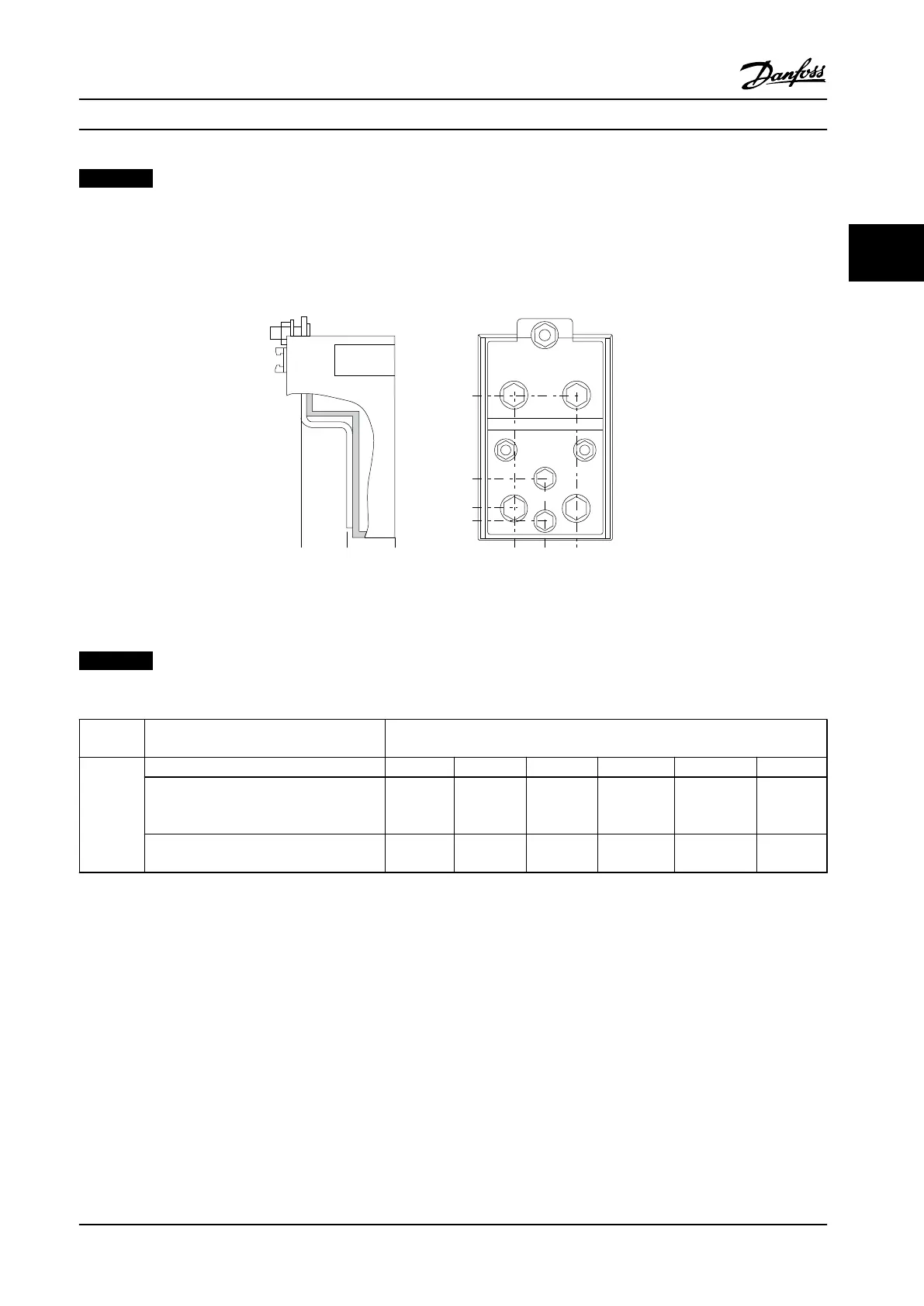
Each terminal allows use of up to four cables with cable lugs or use of standard box lug. Ground is connected to
relevant termination point in the adjustable frequency drive.
If lugs are wider than 39 mm (1.54 in), install supplied barriers on the line power input side of the disconnect.
104[4.1]
35[1.4]
10[0.4]
0[0.0]
0[0.0]
40[1.6]
78[3.1]
0[0.0]
26[1.0]
26[1.0]
176FA271.10
Figure 3.23 Terminal in Detail
NOTICE!
Power connections can be made to positions A or B.
Enclosure
size
Unit type Dimensions [mm]/(inch)
E2
IP00/CHASSIS A B C D E F
250/315 kW (350/425 hp) (400 V) and
355/450–500/630 kW (475/600–650/850 hp)
(690 V)
396 (15.6) 268 (10.6) 333 (13.1) 398 (15.7) 221 (8.7) N/A
315/355–400/450 kW (425/475–550/600 hp)
(400 V)
408 (16.1) 239 (9.4) 319 (12.5) 399 (15.7) 113 (4.4) 153 (6.0)
Table 3.6 Dimensions for Disconnect Terminal
Mechanical Installation Instruction Manual
MG11F522 Danfoss A/S © 08/2014 All rights reserved. 23
3 3

 Loading...


