VLT
®
MICRO
70
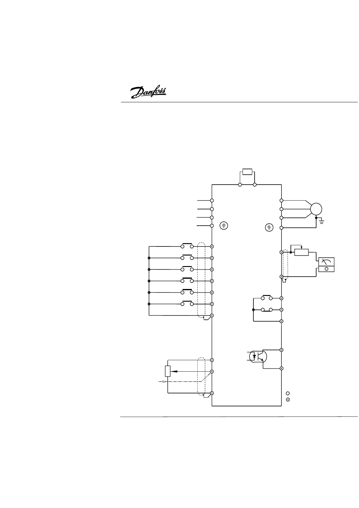
Cableado
El convertidor de frecuencia incorpora dos sistemas de cableado: un circuito principal y
un circuito de control. Los terminales del circuito principal están ubicados en la parte
superior del convertidor. Los del circuito de control están en la parte inferior. Ambos
bloques de terminales están cubiertos por la carcasa de plástico. Levante la parte
goznada de la carcasa para acceder a los mismos. Cerciórese de que se ha
desconectado el suministro de red eléctrica antes efectuar las conexiones. Conecte los
cables a los terminales de acuerdo con el siguiente diagrama. Si no se hace ninguna
conexión a los terminales del circuito de control, la unidad funcionará con el teclado/
display digital.
AFm
Braking Resistor (Option)
Select 80 ohm 120V
/200 ohm 120V
R
S
T
200-240VAC
50/60HZ
(Select two
terminals as
input for single
phase models)
Factory set as
multi-function input terminals
Forward/Stop
Reverse/Stop
Reset
Multi-Step 1
Multi-Step 2
Multi-Step 3
Signal Common
M0
M1
M2
M3
M4
M5
GND
M
Grounding
Trim (1K ohm)
Analog +
output
DC 0-10V –
Factory set as,
Indication of output frequency
Multi-function indication output
contacts 120VAC/28VDC 5A
240VAC 2.5A
Factory set as,
Indication of fault
RA
RB
RC
Multi-function PHC output
48V 50mA below
Factory set as,
Indication of Operation
MO1
MCM
Power for
speed setting
+10V 10mA (max)
AV1
GND
Output Freq. determined
Analog voltage
0-10VDC
VR: 3K-5K ohm
Analog current
4-20mA
Factory set as, output frequency
determined by the potentiometer on
the control panel
R
S
T
E
U
V
W
F
GND
Ground
Control Circuit Terminals
Main Circuit (power) Terminals
B1 B2