1 Introduction
1.1 Purpose of the Manual
These operating instructions provide information for safe
installation and commissioning of the VLT
®
Midi Drive FC
280 frequency converter.
The operating instructions are intended for use by
qualied personnel.
To use the frequency converter safely and professionally,
read and follow the operating instructions. Pay particular
attention to the safety instructions and general warnings.
Always keep these operating instructions with the
frequency converter.
VLT
®
is a registered trademark.
1.2 Additional Resources
Resources available to understand advanced frequency
converter functions and programming:
•
VLT® Midi Drive FC 280 Design Guide.
•
VLT® Midi Drive FC 280 Programming Guide.
Supplementary publications and manuals are available
from Danfoss. See vlt-drives.danfoss.com/Support/Technical-
Documentation/ for listings.
1.3
Document and Software Version
This manual is regularly reviewed and updated. All
suggestions for improvement are welcome. Table 1.1 shows
the document version and the corresponding software
version.
Edition Remarks Software version
MG07A1 The rst edition of this manual 1.0
Table 1.1 Document and Software Version
1.4
Product Overview
1.4.1 Intended Use
The frequency converter is an electronic motor controller
intended for:
•
Regulation of motor speed in response to system
feedback or to remote commands from external
controllers. A power drive system consists of the
frequency converter, the motor, and equipment
driven by the motor.
•
System and motor status surveillance.
The frequency converter can also be used for motor
protection.
Depending on conguration, the frequency converter can
be used in standalone applications or form part of a larger
appliance or installation.
The frequency converter is allowed for use in residential,
industrial, and commercial environments in accordance
with local laws and standards.
NOTICE
In a residential environment this product can cause radio
interference, in which case supplementary mitigation
measures can be required.
Foreseeable misuse
Do not use the frequency converter in applications which
are non-compliant with specied operating conditions and
environments. Ensure compliance with the conditions
specied in chapter 9 Specications.
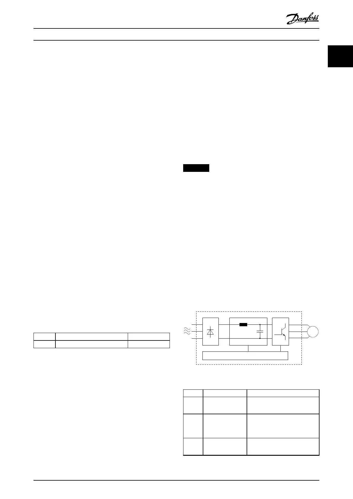
1.4.2 Block Diagram of the Frequency
Converter
Illustration 1.1 is a block diagram of the internal
components of the frequency converter. See Table 1.2 for
their functions.
Illustration 1.1 Frequency Converter Block Diagram
Area Component Functions
1 Mains input
•
AC mains power supply to the
frequency converter.
2 Rectier
•
The rectier bridge converts
the AC input to DC current to
supply inverter power.
3 DC bus
•
Intermediate DC-bus circuit
handles the DC current.
Introduction Operating Instructions
MG07A102 Danfoss A/S © 11/2015 All rights reserved. 3
1 1

 Loading...


