PBI-200114-D 04/2013 COPYRIGHT © Dansensor A/S
30 User Manual EN ISM-3
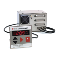
Fig. 6. Flow diagram of ISM-3 with pump. Gas overflow for calibration use is shown
Operation and connection
Operation of ISM-3:
Display 4 digit red LED display
Control 4 front keys. Key function is activated when key is released.
Measuring accuracy Better than +/- 1% of the measured value
+/- 1 digit in calibrated measuring range
Measuring ranges 20.9 % - 1 ppm
Possible connection to the ISM-3:
Gas supply Gas inlet on the back
Relay Max. 48V, 1A. (COMMON, N.O. and N.C.)
Current output (Option) Programmable 0-20 or 4-20 mA, with user-defined scale
(e.g. 0-1 %, 10-20.9 % or 0-100 ppm O
2
).
Voltage output (Option) Programmable 0-10 volt or 2-10 volt with user defined scale
Measure input 10-32VDC external pump control. Consumption 10mA.
RS232C (Option) For serial communication with a PC
All electrical inputs and outputs, except for the RS232C port, is galvanically separated from the internal
electronics by means of optocouplers and/or a relay.