Electronic control description
This section describes key features of the electronic control and how it operates.
Never perform installation, maintenance or service, without disconnecting the AC power
supply.
Basic parameters of the built- in controller can be set via the on board control panel from
inside the unit. See more in operation section page 12.
Extended parameter settings, as well as logging of operation data, is possible through the SD
card interface.
The controller controls the fans, heater, and cooling compressor according to the temperature
in return air ow.
• At power up, the controller will initiate a self test procedure for a few seconds.
• During operation, the evaporator fan will repeatedly circulate the indoor air.
• The compressor will start when the temperature is higher than the setpoint, which then
initiates cooling.
• Then compressor stops at setpoint.
• The high temperature alarm will initiate an alarm on the alarm output when the temp is
higher than 60° C.
• The low temperature alarm will initiate an alarm on the alarm output when the temp is
lower than 1° C.
• The condenser fan operates only when the actual temperature on the condenser surface
requires this.
Alarm connection options can be found on page 11.
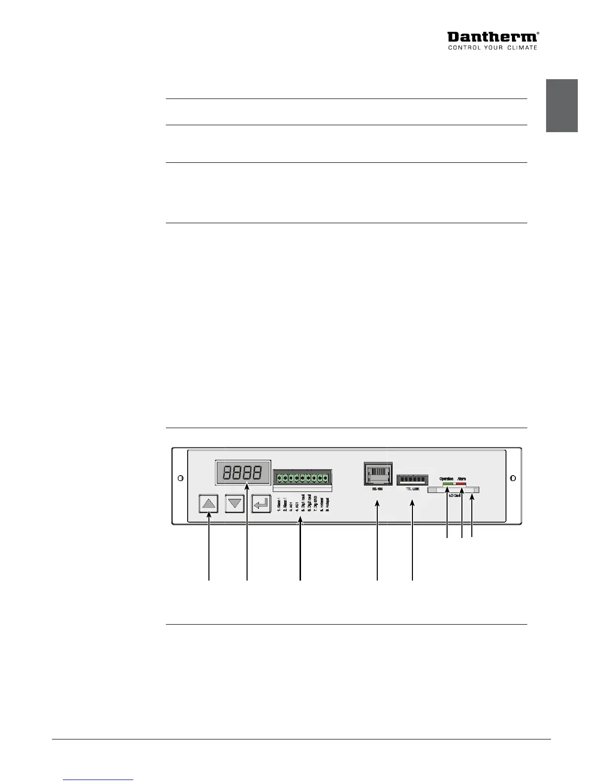
This illustrates the operation panel, seen from inside of the unit.
Keypad Display In/outputs
RS 485
TTL (PC)
Green=OK
Red=alarm
SD card slot
Fig. 6
Introduction
Warning
Embedded
Controller
Control strategy
Operation panel