EasyManua.ls Logo

Dantherm CDP 50 - Main PCB and Wiring Diagrams; PCB Connection Overview; Accessory Cable Routing

Dantherm CDP 50
55 pages
Print Icon
To Next Page IconTo Next Page
To Previous Page IconTo Previous Page
Loading...
26
EN
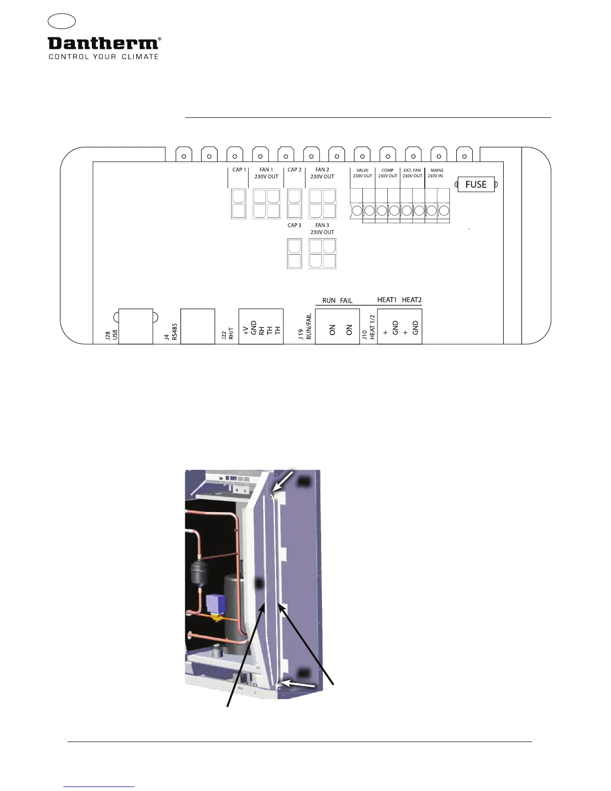
Overview of PCB connections
Routing of cables for
accessories
from terminal rail to PCB
Pull the cable through hole A1 and to the hole A2 to connect to PCB.
The groove B is for use with cable from external RH sensor (not included) as it requires a seperate
groove to avoid interference.
All other cables are to be placed in groove A1-A2
Wiring diagrams-
Page 327
Main PCB and wiring diagrams
A2
A1
B
2A
USB RS485 Ext RH/T Alarm 12VDC
Important:
External RH sensor cable only.
All other cables.

Related product manuals