Do you have a question about the Dantherm CDP 50 and is the answer not in the manual?
Explains how the dehumidifier works using the condensation principle.
Describes how the fan is activated by the hygrostat.
Overview of the unit's display and control interface.
Explains the layout of the 4-digit display.
Describes the default display mode showing relative humidity.
Instructions on how to enter and navigate the menu system.
Guide on setting the relative humidity (rH) parameter.
Indicates changes saved to memory and time of saving.
Indicates that the log file has been saved to USB.
Indicates successful loading of configuration file from USB.
Explains the meaning of the LED indicator colors.
Procedure for cleaning the air inlet filter and drip tray.
Procedure for inspecting the inside of the dehumidifier.
Diagram showing connections on the main PCB.
Instructions for routing accessory cables to the PCB.
Table to localize and solve possible problems or faults.
Advice on contacting service technicians for unresolved issues.
Explains error messages displayed on the CDP unit.
Indicates loss of connection to the Remote Panel.
Indicates out-of-range ambient temperature or humidity.
Indicates a sensor fault, causing the unit to stop.
General notes on dehumidifier maintenance requirements.
Contact information for Dantherm After Sales Support.
Dantherm's offer for preventive maintenance services.
Dantherm's offer for emergency repair services.
Information on Dantherm's network of service partners.
Contact details for service agreement inquiries.
Information on installing and using the electrical heating coil.
List of part numbers for different heating coils.
Description of the heating surface as an accessory.
List of tools required for installation.
Components included in the electrical heating coil kit.
Specifications for electrical heaters.
Illustration of the water heating coil installation.
Provides dimensions for wall ducts and adaptors.
Instructions for using the wall duct adaptor.
Description of the DRC1 wireless remote control panel.
Diagram showing the layout and functions of the remote panel.
Details on the scales used for humidity and temperature.
Information about the USB cable for software updates and power.
Describes how to enter mating mode.
Procedure for mating the DRC1 with the CDP unit.
Explains how to navigate the DRC1 menus.
Steps to take if mating fails.
Description of standard readings displayed on the DRC1.
Describes how to interpret symbols during operation.
Explains how fail conditions are displayed on the remote.
Describes the remote's lock function and its effect.
Instructions for setting humidity and temperature points.
Guide for adjusting the desired humidity level.
Guide for adjusting the desired temperature level.
Instructions for setting the extractor fan speed.
Instructions for setting or resetting the service interval.
Describes stand-by mode 2 for out-of-range ambient conditions.
Explains how sensor failures are detected and displayed.
Details specific fault code for condenser sensor failure.
Guideline values for pool chemicals when added.
Guideline values for pool chemicals with self-production of chlorine.
Advice on using LSI for water parameter acceptance.
Lists Modbus RTU functions and register codes.
Details register parameters for compressor, fan, and valve states.
List of parameters recorded in the data log.
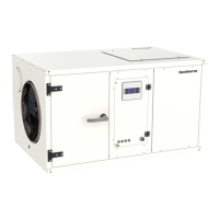
| Brand | Dantherm |
|---|---|
| Model | CDP 50 |
| Category | Dehumidifier |
| Language | English |