14
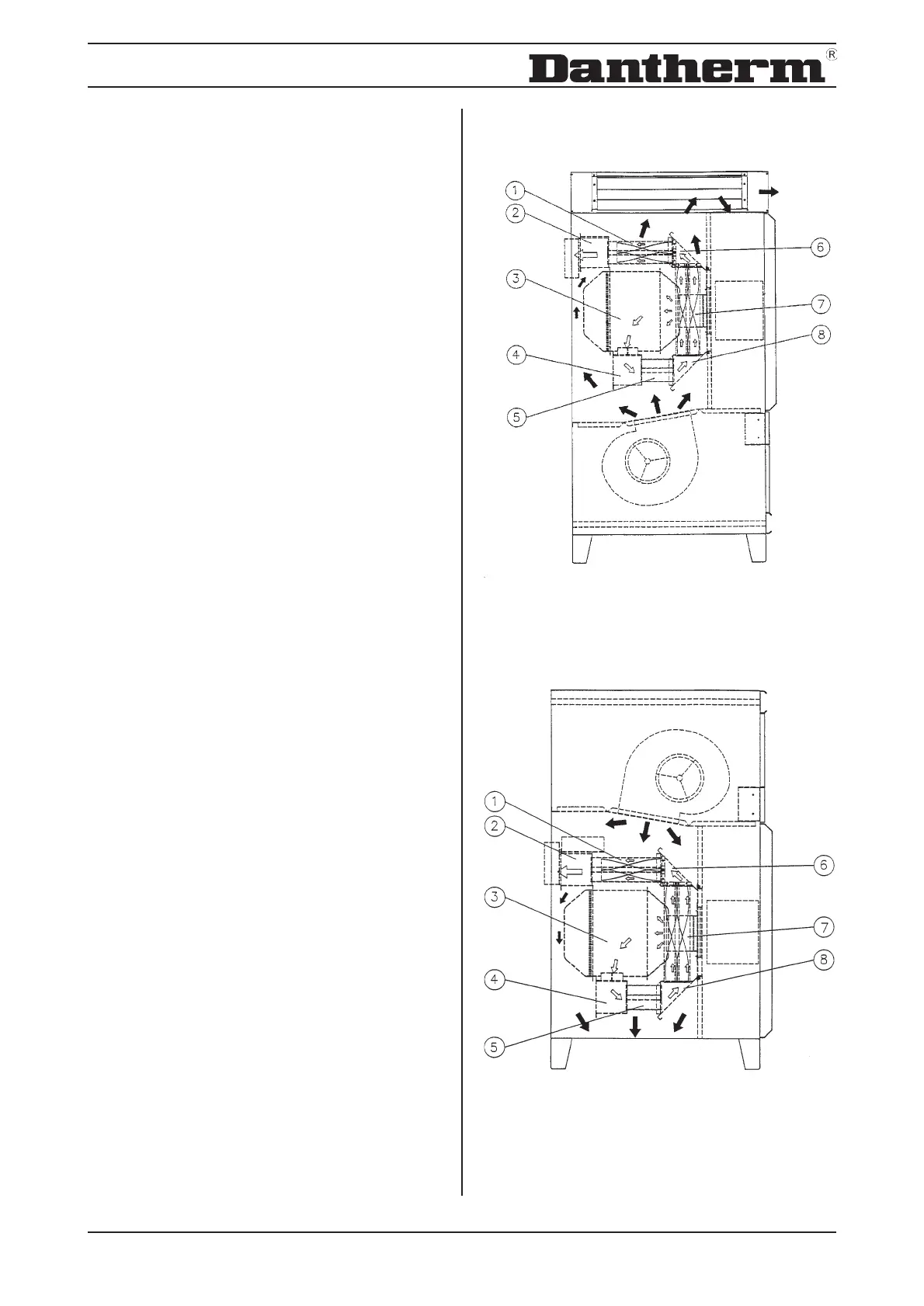
Fig.6 DV 20/30
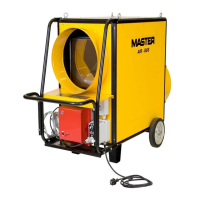
Fig.7 DV M 20
Burner chamber and heat exchanger are cleaned in
the following way (fig. 6/7):
- Remove cover plates above and below the burner.
- Remove the inspection covers (6/8) above and
below the heat exchanger.
- Draw out the turbulators through the upper and
anterior heat exchanger pipes (1/7).
- If there is no visible dirt in the heat exchanger the unit
is reassembled as described above, but in reverse
order. New packing should always be used when
reassembling the unit.
- If it is necessary to clean the heat exchanger the
burner should also be removed and the burner
chamber (3) be checked for dirt.
- Then every heat exchanger tube (1/5/7) is cleaned
by means of a round wire brush. The soot deposits in
the lower assembler (4) are vacuumed out through
the burner opening and the soot in the upper assembler
(2) is vacuumed out through the heat exchanger pipes
by means of a vacuum cleaner.
- Then the turbulators are cleaned and pushed back
into the upper and anterior heat exchanger tubes (1/
7) and the unit is reassembled in reverse order.
4.3 Further Components
All other components in the DV 20/30 units need no
service.
The burner should be checked in accordance with the
instructions of the burner supplier.