6
Fig.1
2.1 Mounting
The unit is delivered placed horizontally on a wooden
pallet. After removing the packing the DV 20/30 unit is
placed on either the supplied stand or directly on an
air intake duct. If the unit is to work without air intake
duct the stand MUST be used, as the air is taken in at
the bottom of the unit.
A duct or an air discharge head is fitted to the air outlet.
DV M 20 is designed only for duct connection and will
therefore have to be mounted directly on the exhaust
duct. The air intake duct is fitted at the top of the unit.
The flue should be connected in accordance with
legal requirements. Flue connection of gas fired units
is to be made only by autho-rized specialists.
On the standard version the burner door is hinged on
the right hand side. The door can be hinged on the left
hand side by taking off the two hinges on the right
hand side, turn them 180° and mount them in the left
door fittings.
* Accessories
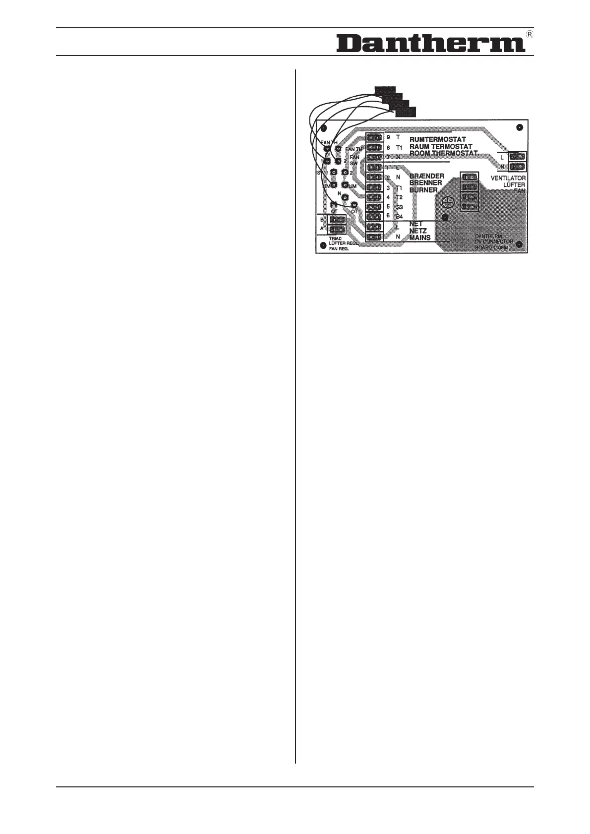
2.2 Electrical Connection
Inside the control panel is a terminal strip on which all
the connections of the unit are located.
1 x 230 V supply voltage is connected through the
terminals L and N (network) and through the earth
terminal.
The room thermostat is connected through the
terminals 7/8 and 9 (room thermostat). The existing
bridges are removed, as the burner will otherwise run
continuously.
A thermostat for 1 x 230V or a week panel 1 x 230V
is used.
The cables for power supply and thermostats can be
passed into the units through the holes at the top or
the bottom. The holes have a covering which can
easily be pierced. The cables are passed into the
control box by means of PG screw-joints.