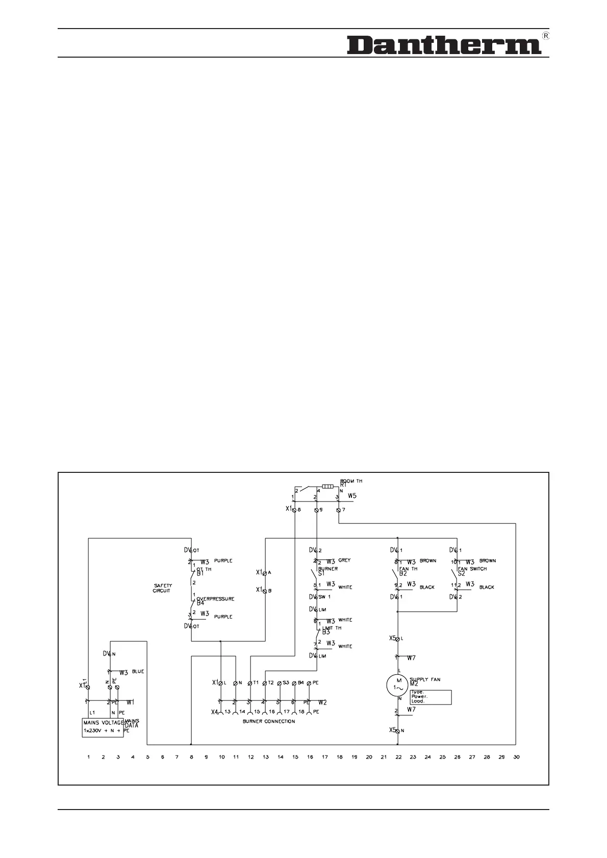
6. Schaltplan / Schemas electriques / Wiring diagram - DV 20/30 -
B1 OT Thermostat 100°C / Thermostat de sécurité 100°C / OT thermostat 100°C
B2 Ventilatorthermostat / Thermostat du ventilateur (FAN) / Fan thermostat (FAN)
B3 Limitthermostat 80°C / Themostat de sécurité 80°C / Limit thermostat 80°C
M2 Ventilatormotor / Moteur du ventilateur / Fan motor
RT Raumthermostat / Thermostat d’ambiance / Room thermostat
S1 Schalter Brenner / Intérrupteur brûleur (on/off) / Burner switch (ON/OFF)
S2 Schalter Ventilator / Intérrupteur ventilateur Auto/Man / Fan switch AUTO/MAN
Wieland Stecker / Fiche Wieland / Wieland plug
L Phasen Anschluss / Raccordement phase / Live
N Nulleiter Anschluss / Neutre / Neutral
T1 Sicherheitskreislauf / Circuit de sécurité / Safety circuit
T2 Sicherheitskreislauf / Circuit de sécurité / Safety circuit
S3 Kontrollampenausgang für Fehler / Borne pour voyant lumineux d’alarme / Control light terminal, failure
B4 Ausgang für Betriebsstundenzähler / Borne pour compteur horaire / Hour meter terminal
18