33 / 47
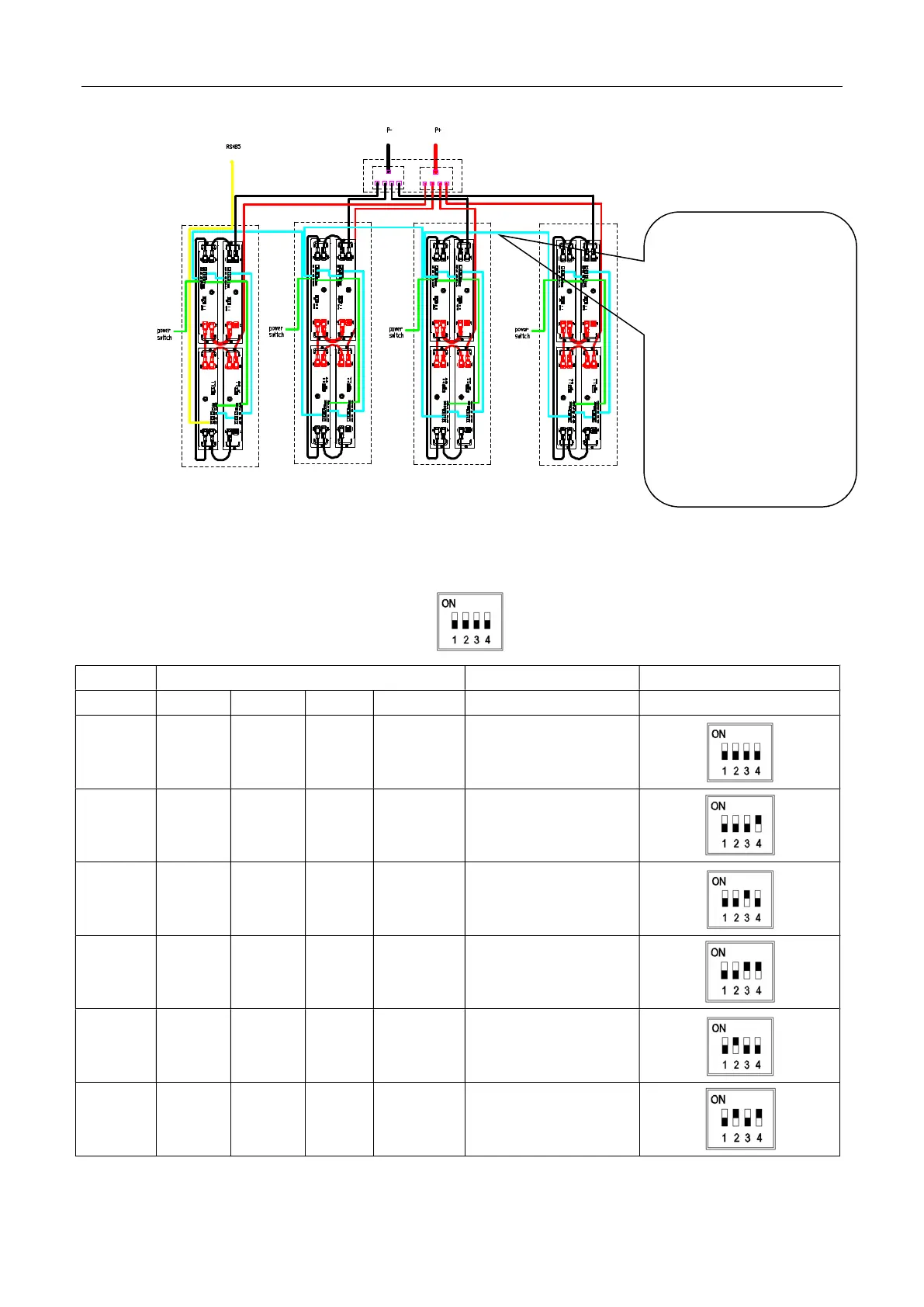
3.5 DIP switch settings
Address
Dial switch position Explain schematic diagram
#1 #2 #3 #4
0 OFF OFF OFF OFF SLAVE1/MASTER
1 OFF OFF OFF ON SLAVE2
2 OFF OFF ON OFF SLAVE3
3 OFF OFF ON ON SLAVE4
4 OFF ON OFF OFF SLAVE5
5 OFF ON OFF ON SLAVE6
9.6k Wh Cabi net -1
9.6k Wh Cabi net -2
9.6k Wh Cabi net -3 9.6k Wh Cabi net -4
BAT 13 BAT 14
BAT 16
BAT 15
BAT 6BAT 5
BAT 2
BAT 9 BAT 10
BAT 1
BAT 4
BAT 7
BAT 12 BAT 11
BAT 3
BAT 8
d. Use the wire harness
(label with CAN1, length
4000mm) to connect from
CAN2 of BAT4 of cabinet-1
to CAN1 of BAT5 of
cabinet-2, from CAN2 of
BAT8 of cabinet-2 to CAN1
of BAT9 of cabinet-3, from
CAN2 of BAT12 of cabinet
-3 to CAN1 of BAT13 of