34 / 47
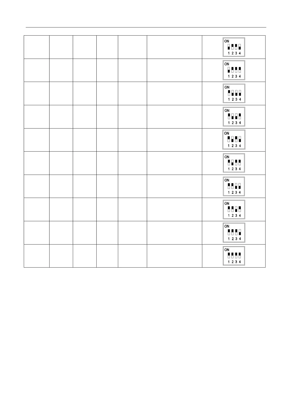
6 OFF ON ON OFF SLAVE7
7 OFF ON ON ON SLAVE8
8 ON OFF OFF OFF SLAVE9
9 ON OFF OFF ON SLAVE10
10 ON OFF ON OFF SLAVE11
11 ON OFF ON ON SLAVE12
12 ON ON OFF OFF SLAVE13
13 ON ON OFF ON SLAVE14
14 ON ON ON OFF SLAVE15
15 ON ON ON ON SLAVE16
3.6 Matching resistor installation
As shown in the figure, a single cabinet connects a matching resistor to the CAN1
communication interface of BAT1, and a matching resistor is connected to the CAN2
communication interface of BAT4. When two cabinet are in parallel, a matching resistor is
connected to the CAN1 communication interface of BAT1 in Cabinet-1. A matching resistor
is connected to the CAN2 communication interface of BAT8 in Cabinet-2. When four
cabinets are connected, a matching resistor is connected to the CAN1 communication