5
TERMINAL DESCRIPTION
TERMINAL #
DESCRIPTION
1
Connect one side of zone 1 loop. Connect other side of loop to
common terminal 2. Open
or short causes alarm.
2 Common (-) Terminal.
3 Connect one side of zone 2 loop. Connect other side of loop to
common terminal 2. Open
or short causes alarm.
4-12 See Terminal Drawing and repeat the above sequence for zones 3
through 8.
13-14 Auxiliary power, regulated 12VDC. Maximum 700mA for all Auxiliary
power outputs.
15-26 See Terminal Drawing and continue above described hookup zones 9
through 16.
27-28 Auxiliary power, regulated 12VDC. Maximum 700mA for all Auxiliary
power outputs.
29 Earth Ground, connect to a cold water pipe, or 6 to 10 foot driven rod.
30-31 AC input, connect a 16.5V 50VA approved transformer.
32-33 Resettable 12VDC 250mA Aux power.(Memory reset and/or Smoke
detector power)
34-36 Form C programmable on board relay output. Tied to auxiliary output
#3.
37 Negative, provided as a convenience for relay connection.
38-39 Form A programmable on board relay output. Tied to auxiliary output
#4.
40-41 Siren driver output to speaker(s). Min speaker rating 30/40 watt at 4, 8,
or 16 ohms). See
page ? for connection diagram. When a 10/15 watt speaker is used,
connect one wire to
terminal 40 or 41 and the other wire to terminal 37.
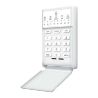
42-45 Connect code pad wires as follows; Green to terminal 42, Yellow to
Terminal 43, Red to
terminal 44, and Black to terminal 45. Maximum run with 7/020 cable is
70 meters.
Maximum run with 14/020 cable is 120 meters. A maximum of 4 code
Pads may be
Connected.
Battery :Leads Connect to 12VDC lead acid rechargeable battery: Black(-) & Red(+).
Do not use a dry cell
battery.
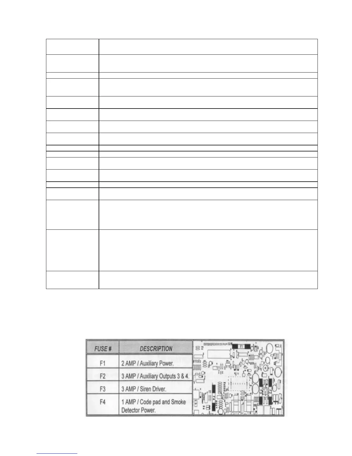
FUSE DESCRIPTION
F1