MENU L – Configure I/O continued
O
p
t
i
on
a
l
S
e
n
s
o
r
#1
V
a
l
v
e
P
o
s
i
t
i
on
E
n
a
b
l
e
:
O
n
C
h
a
nn
e
l
:
U
01
N
o
r
m
a
l
4
-
20
m
A
M
i
n
i
m
u
m
:
0
.
0
M
a
x
i
m
u
m
:
100
.
0
O
ffs
e
t:
0
.
0
V
a
l
u
e
:
92
.
6
%
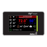
Optional Sensor Screen (one of four on large dap4) The settings of these inputs
are the same as described for the analog input screens described above.
However, the first line that identifies the input is adjustable. The choices are:
*Note: “FreezeStat Temp” appears only optional #1, others have “Hot Gas Temp”
instead. These two choices and “Damper Position” are functional, while others are
for reference display and BMS monitoring purposes only.
A
n
a
l
o
g
O
u
t
pu
t
C
on
f
i
g
Fan
S
p
ee
d
C
h
a
nn
e
l
:
Y
1
A
c
t
i
on
:
D
i
r
ec
t
M
i
n
i
m
u
m
:
0
.
00vd
c
M
a
x
i
m
u
m
:
10
.
0vd
c
Analog Output Screen (one of 6 on large dap4) The top line identifies the function
of the output. The second line indicates physical connection of the output.
Action – Sets the direction that the modulation has on the 10v signal.
DIRECT (default) causes output to be at maximum when modulation is at
maximum. REVERSE causes output to be at minimum when modulation is
at maximum.
Minimum and Maximum - Sets the span of the output signal.