MENU L – CONFIGURE I/O (Factory Level)
Notice: The I/O Configuration menu should only be used by qualified technicians.
Improper setting may prohibit safety functions from working and affect the
operation of controller.
D
i
g
i
t
a
l
I
npu
t
A
I
R
F
L
O
W
S
W
I
T
C
H
C
h
a
nn
e
l
I
D
5
A
c
t
i
on
:
C
l
o
s
e
d
D
e
l
a
y
:
5
s
S
t
a
t
u
s
:
O
p
e
n
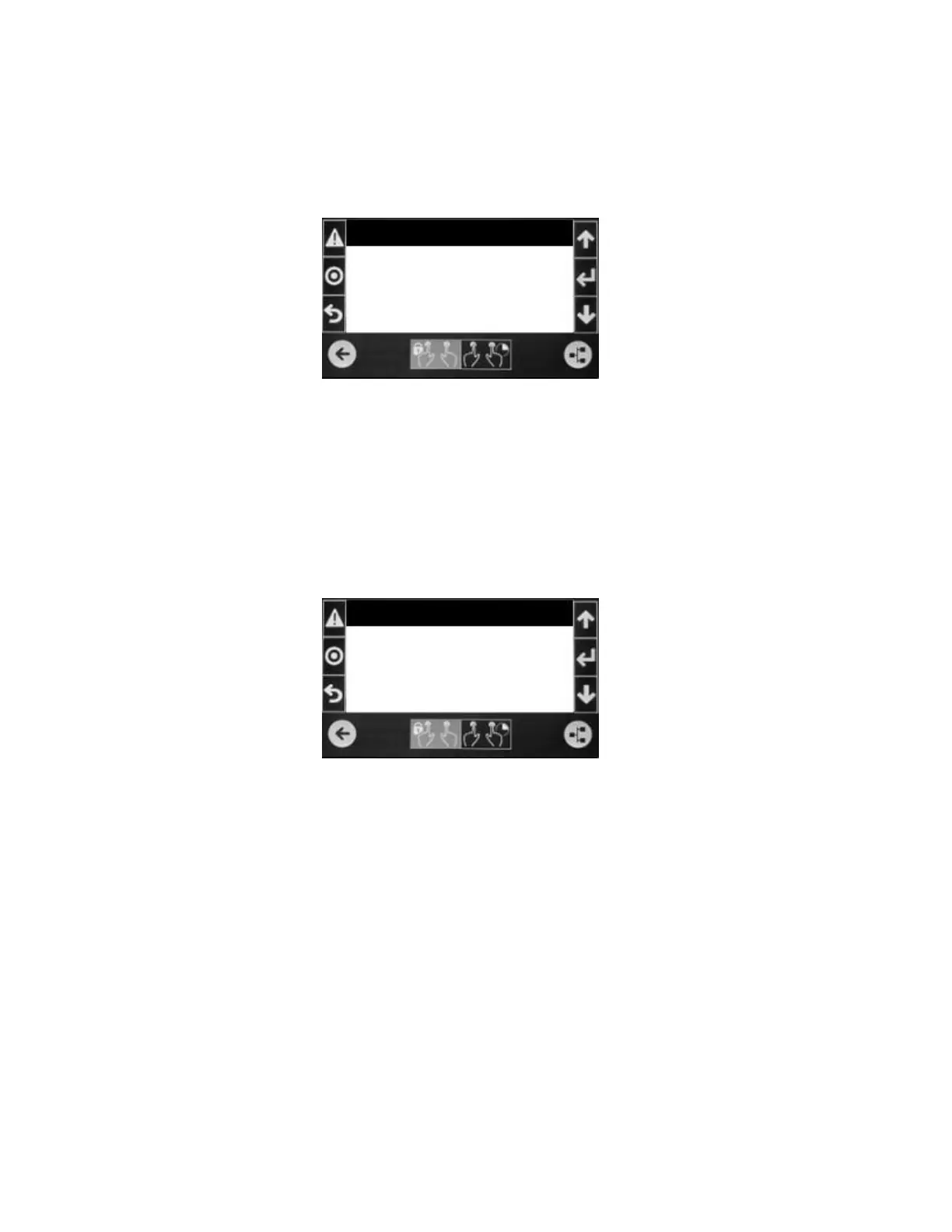
Digital Input Screen (one of many) The top line identifies the function of the input.
The second line indicates which input of the controller that it is wired to.
Action: This is the selection for when the input will be considered on (or in
some cases, in alarm).
Delay: This is the time between the switch and the on status. Range of
adjustment is 0 to 999 seconds with a default value of 5 seconds.
Status: Indicates the current status of the switch connected to the input.
A
n
a
l
o
g
I
npu
t
H
u
m
i
d
i
t
y
S
e
n
s
o
r
E
n
a
b
l
e
:
O
n
C
h
a
nn
e
l
:
U
01
N
o
r
m
a
l
4
-
20
m
A
M
i
n
i
m
u
m
:
0
.
0
M
a
x
i
m
u
m
:
100
.
0
O
ffs
e
t:
0
.
0
V
a
l
u
e
:
51
.
1
%
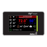
Analog Input Screen (one of many) The top line identifies the function of the
input. The second line indicates if the input is being used (enable on) and which
input of the controller that it is wired to. The third line has the setting for resolution
(Normal or High Resolution) and the type of sensor being used: NTC, PT1000, 0-
1VDC, 0-10VDC, 4-20mA, ON/OFF, 0-5VDC or NTC HT. Not all analog inputs
support all sensor types.
Minimum and Maximum - Sets the span of the sensor. Not shown for
NTC, PT1000 or on/off type sensors.
Offset – The offset value is used to calibrate the sensor. This setting is also
adjustable in the Sensor Calibration menu (service level password).
Value – The current reading of the input including the offset.