DS2 Instruction Manual
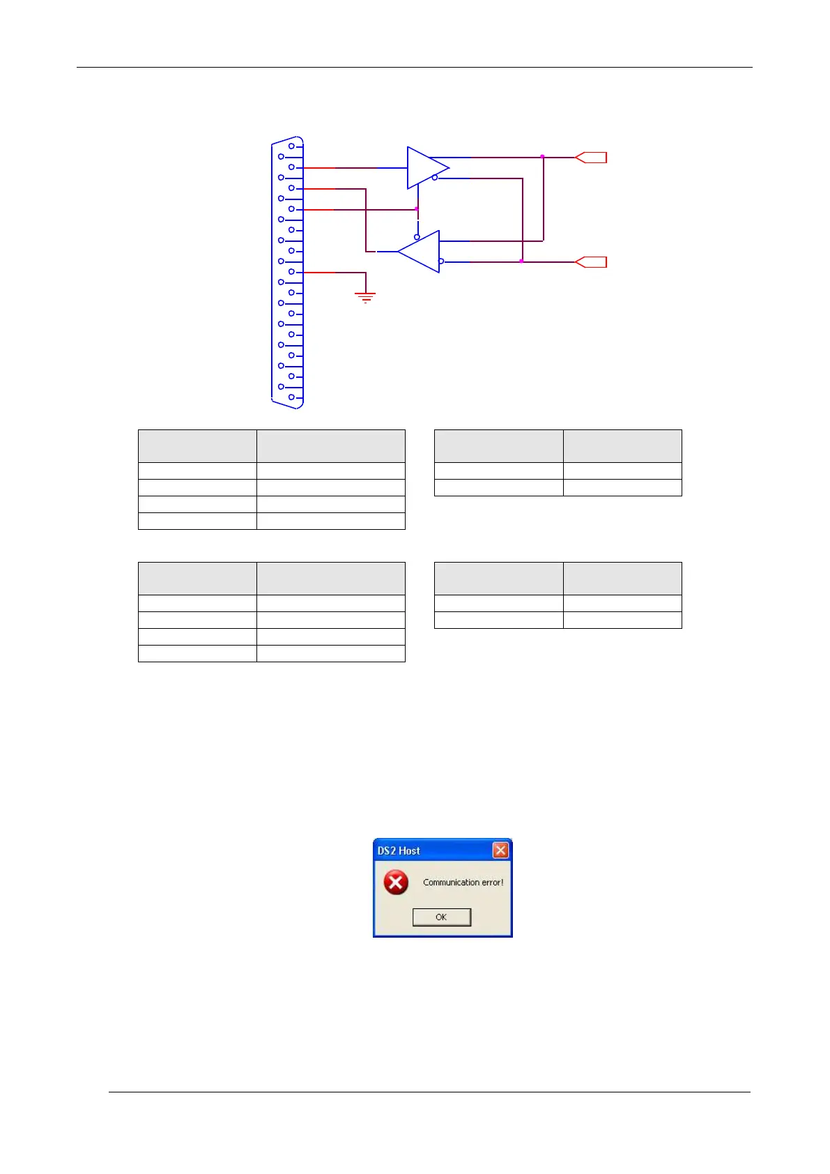
The following figures show the typical diagram of a RS232/RS485 converter.
TXD
TX-
TX+
GND
A
B
RTS
RX+
DB25
7
4
3
2
RXD
TX
RX-
RX
Converter
(RS232-DB25 side)
Converter
(RS232-DB25 side)
The program is ready to function after connecting the PC to the RS485 serial line and powering the
DS2. Select the COM1, COM2, COM3 or COM4 serial communication port and press Connect. A
small window visualises a “Wait please…” message. The program will effect scanning on the serial
line testing separately each transmission speed until reaching the set DS2 speed (please consider
that this operation requires a few seconds). Once connected, the program will memorize the
transmission speed reached on the disk in order to optimise successive connections. This will
reduce the connection time, eliminating the initial scanning testing time.
The following window will appear if the connection fails:
In this case check the electrical connection and device powering.
 Loading...