Instruction Manual DS2
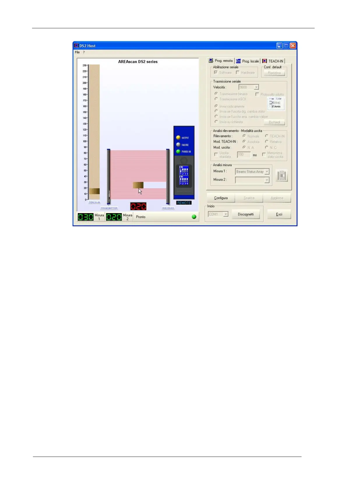
Fig.14
After connection (see previous figure) and according to the local or remote programming, the
graphic on the left side of the user interface’s main window will visualise the following:
the beams and object shape
the Teach-in memorised in the receiver unit
the indicators of the two measurements according to the programming mode selected
local and remote configuration status
The bars that represent the light grid are automatically re-sized according the DS2 model
connected. The Configure button is activated and the Connect button becomes Disconnect.
Passing the cursor over the scanning area, the digital indicator below lights up showing the position
of the beam selected. The same happens in the Teach-in bar.
The current programming mode selected is visualised under the virtual panel. The programming
mode can be changed only using the dip-switch located on the DS2 light grid, also during device
powering. The dip-switch, corresponding to the programming mode, is the only one decoded in real
time. All the other switches require device turning off and re-powering. Misalignments can thus
occur between the real dip-switches and the virtual ones of the interface.
 Loading...