Mounting the Scanner
6 Gryphon™ GFE4400
Table 1. J1 Connector Pins Assignment
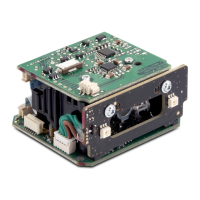
The J1 connection on the GFE4400 scan engine is a Hirose,
DF13C-12P-1.25V,12 circuit connector. For application integration the
recommended mating plug is DF13-12S-1.25C housing with
DF13-12S-1.25C wire crimp terminals.
Figure 2. Interface Board (bottom view)
Pin Number Pin Functionality
1USB D+
2USB D-
3 USB Shield
4 USB Shield
5
EXT_TRIGGER_IN; (input to the base of a transistor, pull
high to activate)
6 RS232 TXD (output from scanner)
7 RS232 RTS (output from scanner)
8 RS232 RXD (input to the scanner)
9 RS232 CTS (input to scanner)
10 DIGITAL_OUT (open collector)
11 +5V (USB Vbus or external power adapter)
12 GND
 Loading...