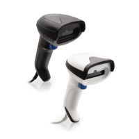
Mounting the Scanner
Integration Guide 11
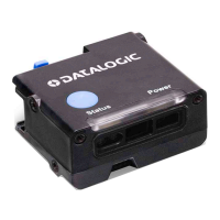
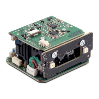
Table 2. J2 Connector Pins
The following table outlines scan engine status assigned to each LED
(with recommended colors).
Pin Number Pin Functionality
1 LED1 Ctrl Signal, Trigger (active low)
2 LED2 Ctrl Signal, Status (open collector active low)
3 LED3, Power, (hard wired to VCC internally)
4 VCC_Out (5v for LED supply)
5Trigger Switch+
6 Trigger Switch- (ground)
L3
POWER
(yellow
ON = Power ON
OFF = Power OFF
L2
STATUS
(green)
ON = Good Read
Blinks = USB enumeration or interface inac-
tive or waiting for change of configuration
L1
TRIGGER
(blue)
ON = External trigger or button pressed or
phase active
Blinks = During transfer of captured image,
or during Flash memory updates
S1 SWITCH Press for manual-controlled trigger
 Loading...