Counter Cutout
Technical Guide 2-11
3. Install the AC/DC Power Supply, the Remote Scale Display cable (if
Remote Display is used) and the interface cable(s) observing the fol-
lowing:
Interface cables (and display cable, if applicable) should be
routed away from all highly inductive electrical devices, like
motors and conveyor belts, and even away from the unit’s
power cable if possible.
Cables should be easy to remove in the event that replace-
ment is required. A little planning now will save a lot of frus-
tration later.
4. Connect and verify all system operations.
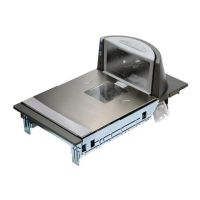
The scanner should be installed so that leading and trailing edges of the L
-Platter are flush with the countertop to enhance smooth, slide-through
scanning (reference the insert in Figure 2-7). Keep in mind that the
debris chutes on both sides of the platter provide the necessary clearance
for proper scale operation if you are installing a scanner/scale (you won’t
need to provide an additional gap for that).
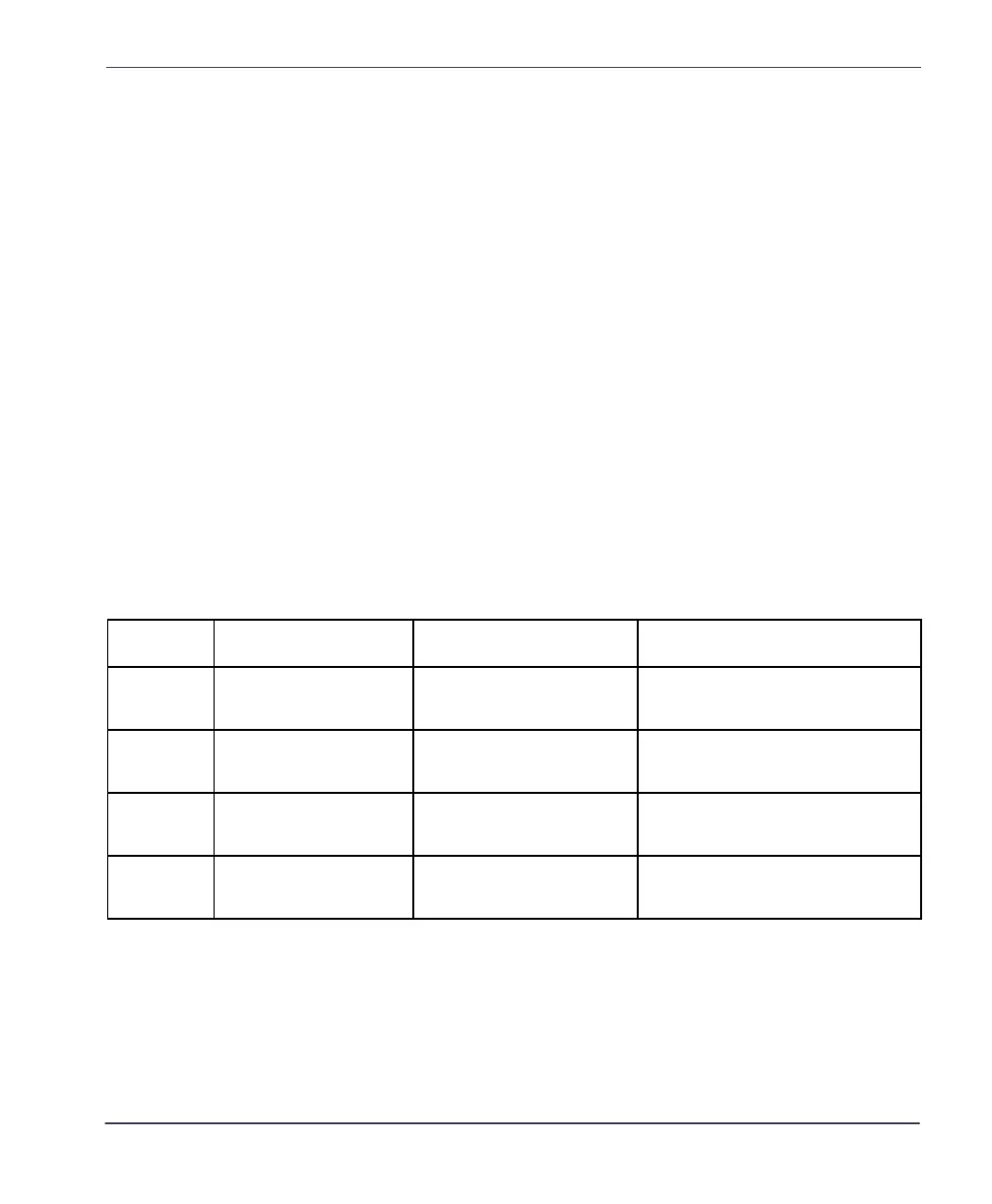
Table 2-1. Cut-Out Dimension References
MODEL(s) TYPE FLANGE/SHELF OPTION DIMENSIONAL REFERENCE
8302/8304
8402/8404
Medium Scanner/Scale Shelf
Figure 2-8
8302/8304
8402/8404
Medium Scanner/Scale Flange
Figure 2-10
8303/8305
8403/8405
Long Scanner/Scale Shelf
Figure 2-12
8303/8305
8403/8405
Long Scanner/Scale Flange
Figure 2-14
 Loading...


